Table of Contents
Advertisement
Quick Links
Advertisement
Table of Contents

Related Manuals for SUTO S130


Summary of Contents for SUTO S130
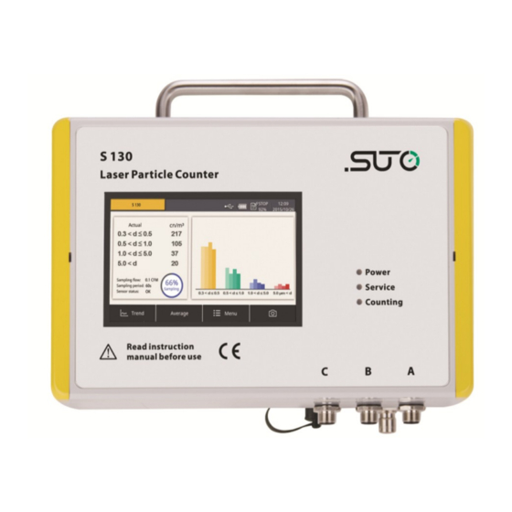
- Page 1 English Instruction and operation manual S130 Laser particle counter...
- Page 2 The device is destined exclusively for the described application. SUTO offers no guarantee for the suitability for any other purpose. SUTO is also not liable for consequential damage resulting from the delivery, capability or use of this device.
-
Page 3: Table Of Contents
8.2.4 Modbus settings................23 8.2.5 Sensor Info..................23 9. LED indicators at the front panel..........24 10. Signal outputs.................24 10.1 Analog output ..............24 10.2 Digital output ..............24 10.3 Alarm output ..............26 11. Optional accessories..............28 12. Calibration................28 13. Maintenance................29 14. Disposal or waste..............29 15. Warranty................29 S130... -
Page 4: Safety Instructions
• Consider all regulations for electrical installations. • The system must be disconnected from any power supply during maintenance. • Any electrical work on system is allowed only by authorized qualified personal. S130... - Page 5 It is not allowed to disassemble the product. ATTENTION! Measurement values can be affected by malfunction! The product must be installed properly and maintained frequently. Otherwise it may lead to wrong measurement values, which can lead to wrong results. S130...
- Page 6 • Before you start to measure, check your measurement point by using a simple filter to see if any rough contamination is present. (Example of such a test device is shown below Ask the supplier 。 if not sure.) S130...
-
Page 7: Application
2. Application 2. Application The S130 is a laser particle counter which is designed to measure particle in compressed air or compressed gases within the permissible operating parameters. For more information about these parameters, see chapter 4. Technical data. The measurement values represent the particle counts per ft , l or m alternately in µg/m... -
Page 8: Technical Data
Dimensions See dimensional drawing on page 10. Display (optional) 5” graphic display, 800 x 480 pixels with touch interface Weight 1.9 kg 4.2 Electrical data Power supply 24 VDC, 10 W without display 24 VDC, 20 W with display S130... -
Page 9: Output Signals
100% @ d > 0.45 μm 4.5 General procedure of particle counting The S130 does not count any particles in the first five minutes. During this period it performs a purge process to ensure that any remaining particles in the system are blown out. -
Page 10: Dimensional Drawing
5. Dimensional drawing 5. Dimensional drawing S130... -
Page 11: Installation
Calibration certificate No P/N 6.1 Installation requirements S130 can be used as a stationary or portable instrument. S130 comes with four mounting brackets for the stationary installation. Mount the brackets from the backside of the instrument at each corner. The brackets enable you to install the instrument on the wall easily. The following are dimensional drawings of two installing methods. - Page 12 6. Installation Method 1 Method 2 S130...
-
Page 13: Installation Procedure
Please consider the following recommendations for a successful measurement result: • All components from the sampling point to the S130 must be oil and grease free. • Ambient and gas temperature must be within the specified ranges. -
Page 14: Electrical Connection
ATTENTION! Avoid contamination with oil or grease! It will lead to very slow measurement or impossible measurement results! 6.3 Electrical connection The S130 comes with three M12 connectors “A”, “B” and “C”. Pin assignment Connector Pin 1 Pin 2 Pin 3... - Page 15 6. Installation Connection to the external displays from SUTO S130 Colour S330/S331 S320 code Signal Terminal Terminal brown A.2 / B.2 white A.3 / B.3 blue A.4 / C.4 black A.5 / C.5 grey brown brown A.2 / B.2 white A.3 / B.3...
-
Page 16: Configuration
• S130 integrated display 7.1 Configuration using the optional service kit If the S130 does not come with a display (Item No: S604 1303), you can configure the S130 using the optional service kit. For more information about the connection diagram, please see chapter 11. -
Page 17: Operations Using The Integrated Display
8. Operations using the integrated display 8. Operations using the integrated display If the S130 comes with a display (Item No: S604 1305), you can view the particle counts in real-time and configure the S130 using the display. 8.1 User interface The screen below shows the user interface provided on the S130 display. -
Page 18: Main Menu
Shows the progress of the sampling or purging process. The S130 instrument purges sampled data in the first five minutes after powered on. During this period, the progress of “Purging” instead of “Sampling” is displayed. -
Page 19: Icons In The Status Bar
8. Operations using the integrated display The menu consists of the following function buttons: Sensor settings To change the S130 sensor settings Location settings To customize the sensor name shown on the top left of the screen Logger To change data logger settings... -
Page 20: Sensor Settings
8. Operations using the integrated display 8.2 Sensor settings As stated in Chapter 7, the S130 is delivered with standard ex-factory configuration or with specific customer settings according to the order. Before starting to measure, you can access sensor settings using the Menu >... -
Page 21: Counter Setting
8. Operations using the integrated display 8.2.2 Counter setting To change the ex-factory counter settings. Unit To select the unit of the counter Sampling period To view the sampling period Average samples To configure the average number of samples in a sampling period S130... -
Page 22: Alarm Settings
8. Operations using the integrated display 8.2.3 Alarm settings S130 provides one alarm relay output through the pin 1 and 2 of connector C (NO, 32 VDC / 200 mA) to trigger an external alarm device. The Alarm settings menu enables you to configure how to trigger the alarm output based particle counts in a specified channel. -
Page 23: Modbus Settings
8. Operations using the integrated display 8.2.4 Modbus settings To change the ex-factory Modbus settings if needed. 8.2.5 Sensor Info To view the sensor information including its type, serial number, and firmware version. S130... -
Page 24: Led Indicators At The Front Panel
10. Signal outputs 10.1 Analog output The S130 provides an analog output range of 4 ... 20 mA. This output is scaled to: • 4 mA = 0 • 20 mA = 100000 cn/m 10.2 Digital output... - Page 25 UNIT16 R / W Alarm threshold R / W Alarm routing UNIT16 R / W The size of channel and the unit of channel is depending on the model (for example, size: “0.3”, “0.5”.., unit: “cn/m ”, “cn/l”..). S130...
-
Page 26: Alarm Output
Please find the different states in the table below. Situation Relay state S130 is powered off OPEN S130 is powered on / The alarm value is not reached CLOSED S130 is powered on / The alarm value is reached OPEN S130... - Page 27 To trigger an external buzzer or alarm light, you need to invert the signal and build an external alarm circuit. The following figure illustrates an example. S130...
-
Page 28: Optional Accessories
The following diagram shows the connection of the service kit, S130, and the computer. Please ensure that either the S130 or the service kit is connected with the power supply because the USB port cannot supply enough power to both these two devices. -
Page 29: Maintenance
15. Warranty SUTO provides a warranty for this product of 24 months covering the material and workmanship under the stated operating conditions from the date of delivery. Please report any findings immediately and within the warranty time. - Page 30 15. Warranty Other claims, especially those for damage occurring outside the instrument are not included unless responsibility is legally binding. Warranty repairs do not extend the period of warranty. ATTENTION! Batteries have a reduced warranty time of 12 month. S130...
- Page 31 S130...
Need help?
Do you have a question about the S130 and is the answer not in the manual?
Questions and answers