
Subscribe to Our Youtube Channel
Related Manuals for Lenovo ThinkCentre m625q


Summary of Contents for Lenovo ThinkCentre m625q
- Page 1 M625q User Guide and Hardware Maintenance Manual Enery Star Machine Types: 10TF, 10TG, 10TH, 10TJ, 10TK, 10TL, 10UY, 10V0, 10V1, and 10V2...
- Page 2 Important Product Information Guide and Appendix A “Notices” on page 67. Second Edition (August 2019) © Copyright Lenovo 2018, 2019. LIMITED AND RESTRICTED RIGHTS NOTICE: If data or software is delivered pursuant to a General Services Administration “GSA” contract, use, reproduction, or disclosure is subject to restrictions set forth in Contract No. GS-...
-
Page 3: Table Of Contents
Appendix B. Trademarks ..69 Replacing the power adapter bracket ..Removing the computer cover ..© Copyright Lenovo 2018, 2019... - Page 4 M625q User Guide and Hardware Maintenance Manual...
-
Page 5: Chapter 1. Overview
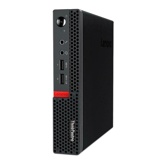
Figure 1. Front view Power indicator Power button Storage drive status indicator Microphone connector Headset connector USB 3.0 connector Illuminated red dot Always On USB 3.0 connector Power indicator This indicator is on when the computer is on. © Copyright Lenovo 2018, 2019... -
Page 6: Rear View
Power button Used to turn on your computer. When you cannot shut down the computer from the operating system, press and hold the power button for four or more seconds to turn off the computer. Storage drive status indicator This indicator is on when the storage drive is in use. Microphone connector Used to connect a microphone to your computer. - Page 7 Figure 2. Rear view Optional connector 1 Optional connector 2 Security-lock slot Wi-Fi antenna slot Ethernet connector USB 2.0 connectors ® USB 2.0 connector DisplayPort connector USB 3.0 connector DisplayPort connector Power adapter connector Optional connector 1 Depending on the computer model, the connector might vary. Optional connector 2 Depending on the computer model, the connector might vary.
-
Page 8: System Board
Wi-Fi antenna slot Used to install the rear Wi-Fi antenna cable connector that is available only on some models. The rear Wi-Fi antenna is installed on the rear Wi-Fi antenna cable connector. Ethernet connector Used to connect an Ethernet cable for network access. USB 2.0 connector Used to connect a USB-compatible device. - Page 9 Figure 3. System board Chapter 1 Overview...
-
Page 10: Machine Type And Model Label
Memory slot Machine type and model label The machine type and model label identifies the computer. When you contact Lenovo for help, the machine type and model information helps support technicians to identify the computer and provide faster service. The machine type and model label is attached on the top of the computer as shown. -
Page 11: Chapter 2. Specifications
Statement on USB transfer rate Depending on many factors such as the processing capability of the host and peripheral devices, file attributes, and other factors related to system configuration and operating environments, the actual transfer © Copyright Lenovo 2018, 2019... - Page 12 rate using the various USB connectors on this device will vary and will be slower than the data rate listed below for each corresponding device. USB device Data rate (Gbit/s) 3.1 Gen 1 3.1 Gen 2 M625q User Guide and Hardware Maintenance Manual...
-
Page 13: Chapter 3. Computer Locks
The cable lock also locks the buttons used to open the computer cover. This is the same type of lock used with many notebook computers. You can order such a cable lock directly from Lenovo by searching for Kensington at: http://www.lenovo.com/support Figure 5. - Page 14 M625q User Guide and Hardware Maintenance Manual...
-
Page 15: Chapter 4. Replacing Hardware
• When installing or replacing an option, use the appropriate instructions explained in this manual along with the instructions that come with the option. • In most areas of the world, Lenovo requires the return of defective CRUs. Information about this will come with the CRU or will come a few days after the CRU arrives. - Page 16 You must remove the screws and panel to access the specific CRU. Optional-service CRUs can be removed and installed by users or, during the warranty period, by a Lenovo service technician. Before replacing FRUs Before replacing any FRU, read the following: •...
-
Page 17: Locating Frus (Including Crus)
Figure 6. Locating FRUs (including CRUs) Notes: • Some of the components are optional. • To replace a component that is not in the list below, contact a Lenovo service technician. For a list of Lenovo Support phone numbers, go to: http://www.lenovo.com/serviceparts-lookup... - Page 18 Number FRU description Self-service CRU Optional-service Vertical stand Power adapter bracket Power adapter Computer cover Dust shield Power cord Internal speaker System board Heat sink Antenna bracket System fan Chassis Bottom cover Memory module M.2 storage drive Storage drive cable Storage drive Storage drive bracket Wi-Fi card shield...
- Page 19 Figure 7. Locating FRUs (including CRUs) Notes: • Some of the components are optional. • To replace a component that is not in the list below, contact a Lenovo service technician. For a list of Lenovo Support phone numbers, go to: http://www.lenovo.com/support/phone...
-
Page 20: Replacing The Keyboard Or Wireless Keyboard
Number FRU description Self-service CRU Optional-service Computer cover Internal speaker Power cord System board Antenna bracket Heat sink Chassis Bottom cover Memory module M.2 storage drive Wi-Fi card shield Wi-Fi card Wi-Fi antennas Coin-cell battery VESA mount bracket Keyboard or wireless keyboard Mouse or wireless mouse Replacing the keyboard or wireless keyboard Note: The wireless keyboard is available only on some models. -
Page 21: Replacing The Mouse Or Wireless Mouse
Replacing the wireless keyboard 1. Remove your old wireless keyboard. 2. Take out the new wireless keyboard from the package. 3. Open the battery compartment cover, and install two AAA batteries according to the polarity indicators. Figure 9. Replacing the wireless keyboard 4. - Page 22 Replacing the wireless mouse 1. Disconnect the USB dongle from your computer. Then, remove your old wireless mouse. 2. Remove the new wireless mouse from the package. 3. Open the battery compartment cover, and install two AAA batteries according to the polarity indicators. a.
- Page 23 Figure 12. Taking out the USB dongle c. Connect the USB dongle to a USB connector. Figure 13. Connecting the USB dongle to a USB connector d. Install the mouse batteries. Chapter 4 Replacing hardware...
- Page 24 Figure 14. Installing the mouse batteries e. Close the battery compartment cover. Figure 15. Closing the battery compartment cover f. Push the power switch to the on position. M625q User Guide and Hardware Maintenance Manual...
-
Page 25: Replacing The Power Adapter
Figure 16. Pushing the power switch to the on position Notes: • The green LED indicates that the mouse is ready for use. • The flashing amber LED indicates a low battery level. • Push the power switch to the off position when you are not using the mouse to extend the battery life. - Page 26 Figure 17. Removing the power adapter b. Remove the power cord. Figure 18. Removing the power cord c. Install the power cord. M625q User Guide and Hardware Maintenance Manual...
- Page 27 Figure 19. Installing the power cord d. Install the power adapter. Figure 20. Installing the power adapter Chapter 4 Replacing hardware...
-
Page 28: Replacing The Vertical Stand
Replacing the vertical stand Attention: Do not open your computer or attempt any repairs before reading the Important Product Information Guide. 1. Remove any media from the drives and turn off all connected devices and the computer. 2. Disconnect all power cords from electrical outlets and disconnect all cables that are connected to the computer. -
Page 29: Replacing The Vesa Mount Bracket
Figure 22. Installing the vertical stand Replacing the VESA mount bracket Attention: Do not open your computer or attempt any repairs before reading the Important Product Information Guide. 1. Remove any media from the drives and turn off all connected devices and the computer. 2. -
Page 30: Replacing The Power Adapter Bracket
Figure 23. Removing the VESA mount bracket b. Install the VESA mount bracket. Figure 24. Installing the VESA mount bracket Replacing the power adapter bracket Attention: Do not open your computer or attempt any repairs before reading the Important Product Information Guide. - Page 31 1. Remove any media from the drives and turn off all connected devices and the computer. 2. Disconnect all power cords from electrical outlets and disconnect all cables that are connected to the computer. 3. Replace the power adapter bracket. a.
-
Page 32: Removing The Computer Cover
Removing the computer cover Attention: Do not open your computer or attempt any repairs before reading the Important Product Information Guide. Removing the computer cover for 10TF, 10TG, 10TH, 10TJ, and 10TK models CAUTION: Before you open the computer cover, turn off the computer and wait several minutes until the computer is cool. - Page 33 Figure 28. Removing the computer cover Removing the computer cover for 10TL, 10UY, 10V0, 10V1, and 10V2 models CAUTION: Before you open the computer cover, turn off the computer and wait several minutes until the computer is cool. 1. Remove any media from the drives and turn off all connected devices and the computer. 2.
-
Page 34: Replacing The Storage Drive For 10Tf, 10Tg, 10Th, 10Tj, And 10Tk Models
Figure 29. Removing the computer cover Replacing the storage drive for 10TF, 10TG, 10TH, 10TJ, and 10TK models Attention: Do not open your computer or attempt any repairs before reading the Important Product Information Guide. 1. Remove any media from the drives and turn off all connected devices and the computer. 2. - Page 35 Figure 30. Removing the storage drive b. Disconnect the storage drive cable from the system board. c. Remove the storage drive bracket. Figure 31. Removing the storage drive bracket d. Install the storage drive bracket. Chapter 4 Replacing hardware...
- Page 36 Figure 32. Installing the storage drive bracket e. Connect the storage drive cable to the system board. f. Install the storage drive. M625q User Guide and Hardware Maintenance Manual...
-
Page 37: Replacing The Storage Drive Cable For 10Tf, 10Tg, 10Th, 10Tj, And 10Tk Models
Figure 33. Installing the storage drive 5. Reinstall the computer cover and reconnect the cables. For details, see “Completing the parts replacement” on page 64. Replacing the storage drive cable for 10TF, 10TG, 10TH, 10TJ, and 10TK models Attention: Do not open your computer or attempt any repairs before reading the Important Product Information Guide. -
Page 38: Replacing The System Fan For 10Tf, 10Tg, 10Th, 10Tj, And 10Tk Models
Figure 34. Removing the storage drive cable b. Install the storage drive cable. Figure 35. Installing the storage drive cable 6. Reinstall the computer cover and reconnect the cables. For details, see “Completing the parts replacement” on page 64. Replacing the system fan for 10TF, 10TG, 10TH, 10TJ, and 10TK models Attention: Do not open your computer or attempt any repairs before reading the Important Product Information Guide. - Page 39 2. Disconnect all power cords from electrical outlets and disconnect all cables that are connected to the computer. 3. Remove the computer cover. For details, see “Removing the computer cover” on page 28. 4. Disconnect the system fan cable from the system fan connector on the system board. See “System board”...
-
Page 40: Replacing The Heat Sink
Figure 37. Installing the system fan 6. Connect the system fan cable to the system fan connector on the system board. See “System board” on page 4. 7. Reinstall the computer cover and reconnect the cables. For details, see “Completing the parts replacement”... - Page 41 Figure 38. Removing the heat sink b. Install the heat sink. Figure 39. Installing the heat sink 5. Reinstall the computer cover and reconnect the cables. For details, see “Completing the parts replacement” on page 64. Chapter 4 Replacing hardware...
- Page 42 Replacing the heat sink for 10TL, 10UY, 10V0, 10V1, and 10V2 models 1. Remove any media from the drives and turn off all connected devices and the computer. 2. Disconnect all power cords from electrical outlets and disconnect all cables that are connected to the computer.
-
Page 43: Replacing The Internal Speaker
Figure 41. Installing the heat sink 5. Reinstall the computer cover and reconnect the cables. For details, see “Completing the parts replacement” on page 64. Replacing the internal speaker Attention: Do not open your computer or attempt any repairs before reading the Important Product Information Guide. -
Page 44: Replacing The Wi-Fi Card
Figure 42. Removing the internal speaker b. Install the internal speaker. Figure 43. Installing the internal speaker 6. Connect the internal speaker cable to the internal speaker connector on the system board. 7. Reinstall the computer cover and reconnect the cables. For details, see “Completing the parts replacement”... - Page 45 2. Disconnect all power cords from electrical outlets and disconnect all cables that are connected to the computer. 3. Remove the computer cover. For details, see “Removing the computer cover” on page 28. 4. Remove the storage drive if necessary. For details, see “Replacing the storage drive for 10TF, 10TG, 10TH, 10TJ, and 10TK models”...
- Page 46 Figure 46. Removing the Wi-Fi card d. Install the Wi-Fi card. Figure 47. Installing the Wi-Fi card e. Connect the Wi-Fi antennas. Figure 48. Connecting the Wi-Fi antennas f. Install the Wi-Fi card shield. M625q User Guide and Hardware Maintenance Manual...
- Page 47 Figure 49. Install the Wi-Fi card shield • Type 2 a. Remove the Wi-Fi card shield. Figure 50. Removing the Wi-Fi card shield b. Disconnect the Wi-Fi antennas. Figure 51. Disconnecting the Wi-Fi antennas Chapter 4 Replacing hardware...
- Page 48 c. Remove the Wi-Fi card. Figure 52. Removing the Wi-Fi card d. Install the Wi-Fi card. Figure 53. Installing the Wi-Fi card e. Connect the Wi-Fi antennas. Figure 54. Connecting the Wi-Fi antennas f. Install the Wi-Fi card shield. M625q User Guide and Hardware Maintenance Manual...
-
Page 49: Replacing The Wi-Fi Antennas
Figure 55. Install the Wi-Fi card shield 7. Reinstall the computer cover and reconnect the cables. For details, see “Completing the parts replacement” on page 64. Replacing the Wi-Fi antennas Attention: Do not open your computer or attempt any repairs before reading the Important Product Information Guide. - Page 50 Figure 56. Disconnecting the front Wi-Fi antenna cable from the Wi-Fi card b. Remove the front Wi-Fi antenna. Figure 57. Removing the front Wi-Fi antenna c. Install the front Wi-Fi antenna. M625q User Guide and Hardware Maintenance Manual...
- Page 51 Figure 58. Installing the front Wi-Fi antenna d. Connect the front Wi-Fi antenna cable to the Wi-Fi card. Figure 59. Connecting the front Wi-Fi antenna cable to the Wi-Fi card 6. Reinstall the computer cover and reconnect the cables. For details, see “Completing the parts replacement”...
- Page 52 4. Remove the storage drive if necessary. For details, see “Replacing the storage drive for 10TF, 10TG, 10TH, 10TJ, and 10TK models” on page 30. 5. Disconnect the rear Wi-Fi antenna cable from the Wi-Fi card. 6. Replace the rear Wi-Fi antenna. Note: Record the cable routing before removing the rear Wi-Fi antenna cable.
- Page 53 c. Remove the rear Wi-Fi antenna cable. Figure 62. Removing the rear Wi-Fi antenna cable d. Install the rear Wi-Fi antenna cable. Figure 63. Installing the rear Wi-Fi antenna cable e. Install the screw cover to secure the rear Wi-Fi antenna cable. Chapter 4 Replacing hardware...
-
Page 54: Replacing The Antenna Bracket
Figure 64. Installing the screw cover to secure the rear Wi-Fi antenna cable f. Install the rear Wi-Fi antenna. Figure 65. Installing the rear Wi-Fi antenna 7. Connect the rear Wi-Fi antenna cable to the Wi-Fi card. 8. Reinstall the computer cover and reconnect the cables. For details, see “Completing the parts replacement”... - Page 55 2. Disconnect all power cords from electrical outlets and disconnect all cables that are connected to the computer. 3. Remove the computer cover. For details, see “Removing the computer cover” on page 28. 4. Remove the storage drive. For details, see “Replacing the storage drive for 10TF, 10TG, 10TH, 10TJ, and 10TK models”...
- Page 56 Figure 67. Removing the antenna bracket c. Install the antenna bracket. Figure 68. Installing the antenna bracket d. Install the storage drive assembly bracket. M625q User Guide and Hardware Maintenance Manual...
- Page 57 Figure 69. Installing the storage drive assembly bracket 7. Reinstall the computer cover and reconnect the cables. For details, see “Completing the parts replacement” on page 64. Replacing the antenna bracket for 10TL, 10UY, 10V0, 10V1, and 10V2 models 1. Remove any media from the drives and turn off all connected devices and the computer. 2.
-
Page 58: Replacing The Coin-Cell Battery
Figure 70. Removing the antenna bracket b. Install the antenna bracket. Figure 71. Installing the antenna bracket 6. Reinstall the computer cover and reconnect the cables. For details, see “Completing the parts replacement” on page 64. Replacing the coin-cell battery Attention: Do not open your computer or attempt any repairs before reading the Important Product Information Guide. - Page 59 The coin-cell battery normally requires no charging or maintenance throughout its life; however, no coin-cell battery lasts forever. If the coin-cell battery fails, the date, time, and configuration information (including passwords) are lost. An error message is displayed when you turn on the computer. 1.
-
Page 60: Replacing The Bottom Cover
c. Install the coin-cell battery. Figure 74. Removing the microprocessor d. Press the coin-cell battery downward until it snaps into position. Figure 75. Installing the microprocessor 7. Reinstall the computer cover and reconnect the cables. For details, see “Completing the parts replacement”... - Page 61 2. Disconnect all power cords from electrical outlets and disconnect all cables that are connected to the computer. 3. Remove the computer cover. For details, see “Removing the computer cover” on page 28. 4. Replace the bottom cover. a. Remove the bottom cover. Figure 76.
-
Page 62: Replacing The Memory Module
Replacing the memory module Attention: Do not open your computer or attempt any repairs before reading the Important Product Information Guide. 1. Remove any media from the drives and turn off all connected devices and the computer. 2. Disconnect all power cords from electrical outlets and disconnect all cables that are connected to the computer. -
Page 63: Replacing The M.2 Storage Drive
Figure 80. Installing the memory module d. Close the memory module retainer. Figure 81. Closing the memory module retainer 6. Reinstall the computer cover and reconnect the cables. For details, see “Completing the parts replacement” on page 64. Replacing the M.2 storage drive Attention: Do not open your computer or attempt any repairs before reading the Important Product Information Guide. - Page 64 Figure 82. Unlocking the M.2 storage drive clip b. Remove the M.2 storage drive. Figure 83. Removing the M.2 storage drive c. Install the M.2 storage drive. Figure 84. Installing the M.2 storage drive d. Lock the M.2 storage drive clip. M625q User Guide and Hardware Maintenance Manual...
-
Page 65: Replacing The System Board And Chassis
Figure 85. Locking the M.2 storage drive clip 6. Reinstall the computer cover and reconnect the cables. For details, see “Completing the parts replacement” on page 64. Replacing the system board and chassis Attention: Do not open your computer or attempt any repairs before reading the Important Product Information Guide. - Page 66 Figure 86. Removing the screws that secure the system board b. Remove the system board. Figure 87. Removing the system board c. Install the system board. M625q User Guide and Hardware Maintenance Manual...
- Page 67 Figure 88. Installing the system board d. Install the screws to secure the system board. Figure 89. Installing the screws to secure the system board 16. Route all the cables that you disconnected from the failing system board, and then reconnect the cables to the new system board.
-
Page 68: Completing The Parts Replacement
Completing the parts replacement Completing the parts replacement for 10TF, 10TG, 10TH, 10TJ, and 10TK models After completing the installation or replacement for all parts, reinstall the computer cover and reconnect the cables. To reinstall the computer cover and reconnect the cables to your computer, do the following: 1. - Page 69 Figure 91. Reinstalling the dust shield 6. Place the computer in an upright position. 7. If a locking device is available, use it to lock the computer. 8. Reconnect the external cables and power cords to the corresponding connectors on the computer. Completing the parts replacement for 10TL, 10UY, 10V0, 10V1, and 10V2 models After completing the installation or replacement for all parts, reinstall the computer cover and reconnect the cables.
- Page 70 Figure 92. Reinstalling the computer cover 4. Install the screw to secure the computer cover. 5. Place the computer in an upright position. 6. If a locking device is available, use it to lock the computer. 7. Reconnect the external cables and power cords to the corresponding connectors on the computer. M625q User Guide and Hardware Maintenance Manual...
-
Page 71: Appendix A. Notices
Lenovo representative for information on the products and services currently available in your area. Any reference to a Lenovo product, program, or service is not intended to state or imply that only that Lenovo product, program, or service may be used. Any functionally equivalent product, program, or service that does not infringe any Lenovo intellectual property right may be used instead. - Page 72 M625q User Guide and Hardware Maintenance Manual...
-
Page 73: Appendix B. Trademarks
LENOVO, LENOVO logo, and the THINKCENTRE logo are trademarks of Lenovo. DisplayPort is a trademark of the Video Electronics Standards Association. VESA is a trademark of the Video Electronics Standards Association. All other trademarks are the property of their respective owners. © 2019 Lenovo. © Copyright Lenovo 2018, 2019... - Page 74 M625q User Guide and Hardware Maintenance Manual...
Need help?
Do you have a question about the ThinkCentre m625q and is the answer not in the manual?
Questions and answers