Advertisement
Advertisement
Table of Contents

Related Manuals for MTD Yardworks 31AS33BE515


Summary of Contents for MTD Yardworks 31AS33BE515
- Page 1 Safety • Assembly • Operation • Adjustments • Maintenance • Troubleshooting • Parts Lists • Warranty OPERATOR’S MANUAL IMPORTANT: READ SAFETY RULES AND INSTRUCTIONS CAREFULLY BEFORE OPERATION. FOR CUSTOMER ASSISTANCE CALL 1-866-523-5218 769-06212 PRINTED IN U.S.A. 06.24.10...
-
Page 2: Table Of Contents
To The Owner Thank You Thank you for purchasing your new equipment. It was carefully The manufacturer reserves the right to change product engineered to provide excellent performance when properly specifications, designs and equipment without notice and operated and maintained. without incurring obligation. -
Page 3: Safe Operation Practices
Important Safe Operation Practices WARNING! This symbol points out important safety instructions which, if not followed, could endanger the personal safety and/or property of yourself and others. Read and follow all instructions in this manual before attempting to operate this machine. Failure to comply with these instructions may result in personal injury. - Page 4 Safe Handling of Gasoline Never run an engine indoors or in a poorly ventilated area. Engine exhaust contains carbon monoxide, an odorless To avoid personal injury or property damage use extreme care and deadly gas. in handling gasoline. Gasoline is extremely flammable and the Do not operate machine while under the influence of vapors are explosive.
- Page 5 Clearing a Clogged Discharge Chute According to the Consumer Products Safety Commission (CPSC) and the U.S. Environmental Protection Agency (EPA), Hand contact with the rotating impeller inside the discharge this product has an Average Useful Life of seven (7) years, chute is the most common cause of injury associated with snow or 60 hours of operation.
- Page 6 Safety Symbols This page depicts and describes safety symbols that may appear on this product. Read, understand, and follow all instructions on the machine before attempting to assemble and operate. Symbol Description READ THE OPERATOR’S MANUAL(S) Read, understand, and follow all instructions in the manual(s) before attempting to assemble and operate WARNING—...
-
Page 7: Assembly & Set-Up
Assembly & Set-Up Assembly NOTE: Remove all loose parts and any packing material before assembling. Setting Up The Handle Cut and remove the cable tie (if present) securing upper handle to lower handle. NOTE: Be aware of the three loosely fitted cable ties attached to the lower handle that will be utilized later to secure the cables. - Page 8 Set-Up Tire Pressure WArning: Under any circumstance do not exceed Shear Pins manufacturer’s recommended psi. Equal tire Replacement shear pins and cotter pins are provided for your pressure should be maintained at all times. Excessive convenience. Store these safely until needed. pressure when seating beads may cause tire/rim assembly to burst with force sufficient to cause serious injury.
- Page 9 While standing in the operator’s position (behind the snow thrower) engage the auger. Allow the auger to remain engaged for approximately 10 seconds before releasing the auger control. Repeat this several times. With the engine running in the FAST position and the auger control in the disengaged “up”...
-
Page 10: Controls
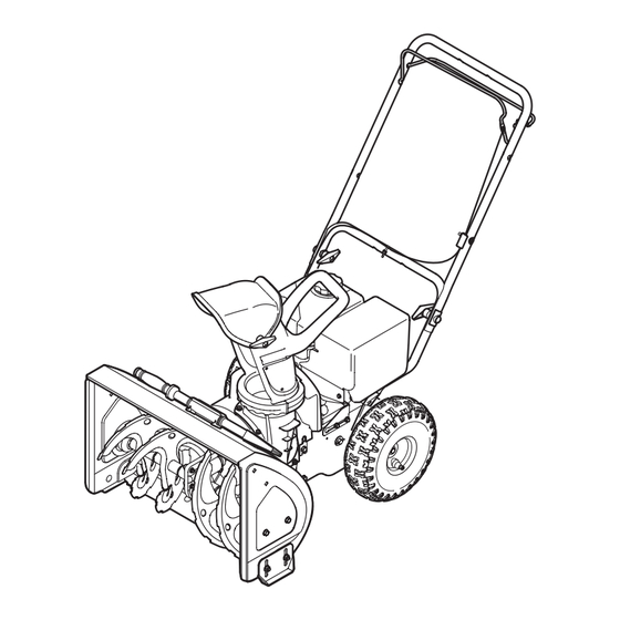
Controls and Features Upper Handle Upper Handle Upper Handle Auger Control Auger Control Auger Control Drive Drive Drive Control Control Control Chute Handle Chute Assembly Chute Handle Chute Handle Chute Assembly Chute Assembly Clean-out Tool Clean-out Tool Clean-out Tool Auger Shave Plate Auger Auger... - Page 11 Chute Clean-Out Tool WARNING! Never use your hands to clear a clogged chute assembly. Shut off engine and remain behind handles until all moving parts have stopped before unclogging. The chute clean-out tool is conveniently fastened to the rear of the auger housing with a mounting clip.
-
Page 12: Operation
Operation Starting and Stopping the Engine Replacing Shear Pins Refer to the Engine Operator’s Manual packed with your snow The augers are secured to the spiral shaft with two shear pins thrower for instructions on starting and stopping the engine. and cotter pins. -
Page 13: Maintenance & Adjustment
Maintenance & Adjustments Maintenance Shave Plate and Skid Shoes The shave plate and skid shoes on the bottom of the snow General Recommendations thrower are subject to wear. These should be checked • Always observe safety rules when performing any type of periodically and replaced when necessary. - Page 14 Lubrication Auger Shaft At least once a season, remove the shear pins from the auger Lubricate pivot points on the auger control and drive shaft. Spray lubricant inside the shaft and around the spacers and control with a light engine oil once a season, see Fig. 6-2. the flange bearings found at either end of the shaft.
-
Page 15: Service
Service Augers Auger Belt Tip the snow thrower up and forward so that it rests on The augers are secured to the spiral shaft with four shear pins and the auger housing. Remove the belt keeper (Refer to Fig. cotter pins. If you hit a foreign object or ice jam, the snow thrower 7-3). - Page 16 Drive Belt NOTE: Replace the drive belt before reassembling the new auger belt. Tip the snow thrower up and forward so that it rests on the auger housing. Remove the spring that connects the transmission to a bolt on the engine frame. See Fig. 7-3. NOTE: It may be easier to first remove the flange lock nut, then use needle-nosed pliers to firmly grip spring and remove from bolt.
-
Page 17: Troubleshooting
Troubleshooting Problem Cause Remedy Excessive vibration Loose parts or damaged auger. Stop engine immediately and disconnect spark plug wire. Check for possible damage. Tighten all bolts and nuts. Repair as needed. If the problem persists, take unit to an authorized service dealer. Unit fails to self-propel Drive belt loose or damaged. -
Page 18: Replacement Parts
Replacement Parts Component Part Number and Description 954-04014 Auger Drive Belt 954-04013 Wheel Drive Belt 738-04124A Shear Pin, 1.50 714-04040 Bow-tie Cotter Pin 784-5580 Skid Shoe, Standard 784-06439 Skid Shoe, Polymer (optional) 731-2643 Chute Clean-out Tool 790-00117 Shave Plate, 22” NOTE: Download a complete Parts Manual, refer to customer support on page 2. -
Page 19: Warranty
4 YEAR LIMITED WARRANTY For FOUR YEARS from the date of retail purchase within Canada, YARDWORKS CANADA will, at its option, repair or replace, for the original purchaser, free of charge, any part or parts found to be defective in material or workmanship. This warranty does not cover: 1. -
Page 20: Emission Control Warranty Statement
Any warranted part that is not scheduled for replacement as required maintenance in the written instructions supplied, is warranted for the warranty period stated above. If the part fails during the period of warranty coverage, the part will be repaired or replaced by MTD Consumer Group Inc according to subsection (4) below. - Page 21 Add-on or modified parts that are not exempted by the Air Resources Board may not be used. The use of any non-exempted add-on or modified parts by the ultimate purchaser will be grounds for disallowing a warranty claims. MTD Consumer Group Inc will not be liable to warrant failures of warranted parts caused by the use of a non-exempted add-on or modified part.
- Page 22 Notes...
Need help?
Do you have a question about the Yardworks 31AS33BE515 and is the answer not in the manual?
Questions and answers
Please identify the name of this part.
The name of the MTD part with the number Yardworks 31AS33BE515 is "Yardworks 31AS33BE515 MTD Manual."
This answer is automatically generated