Table of Contents
Advertisement
Service Manual
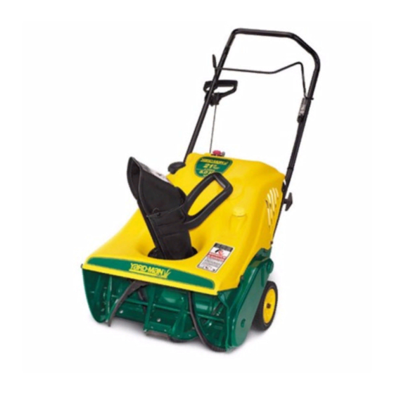
31AS2B5 Snow Thrower
IMAGE SHOWS YARD-MAN UNIT
NOTE: These materials are for use by trained technicians who are experienced in the service and repair of outdoor power
equipment of the kind described in this publication, and are not intended for use by untrained or inexperienced individuals.
These materials are intended to provide supplemental information to assist the trained technician. Untrained or inexperienced
individuals should seek the assistance of an experienced and trained professional. Read, understand, and follow all instructions
and common sense when working on power equipment. This includes the contents of the product's Operators Manual, supplied
with the equipment. No liability can be accepted for any inaccuracies or omission in this publication, although care has been
taken to make it as complete and accurate as possible at the time of publication. However, due to the variety of outdoor power
equipment and continuing product changes that occur over time, updates will be made to these instructions from time to time.
Therefore, it may be necessary to obtain the latest materials before servicing or repairing a product. The company reserves the
right to make changes at any time to this publication without prior notice and without incurring an obligation to make such
changes to previously published versions. Instructions, photographs and illustrations used in this publication are for reference
use only and may not depict actual model and component parts. © Copyright 2005 MTD Products Inc. All Rights Reserved
MTD Products LLC - Product Training and Education Department
FORM NUMBER 769-01416
9/2004
Advertisement
Table of Contents

Summary of Contents for MTD 31AS2B5
- Page 1 Instructions, photographs and illustrations used in this publication are for reference use only and may not depict actual model and component parts. © Copyright 2005 MTD Products Inc. All Rights Reserved MTD Products LLC - Product Training and Education Department...
-
Page 3: Table Of Contents
TABLE OF CONTENTS General Information ... 1 Controls ... 1 Auger ... 1 A/C Starter ... 1 Back of Unit ... 2 Muffler ... 2 Shave Plate ... 2 Discharge Chute ... 3 Auger Drive Belt Replacement ... 3 Auger Removal ... 4 Spark Plug Access ... -
Page 5: General Information
31AS2B5-711 Snow Thrower 31AS2B5-711 Yard-Man Version Snow Thrower Model Number #31AS2B5- 711 Serial Number 1E074B20005 NOTE: The equipment that was used to write this section was a prototype and was without labels. There may be subtle differences between prototypes and production equipment but the disassembly procedures preformed will remain the same. -
Page 6: Back Of Unit
switch and the A.C. plug connector with starter button that is used for the electric start. See Figure 3. Key Switch 110 A/C Plug Figure 3 BACK OF UNIT The Model tag is located on the back of the unit and includes phone numbers for customer assistance: Troy- Bilt 330-558-5520 or 1-800-520-5520. -
Page 7: Discharge Chute
DISCHARGE CHUTE The mitten grip handle on the snow chute allows easy adjustment side to side. See Figure 7. Figure 7 AUGER DRIVE BELT REPLACEMENT 8.1. Remove the five (5) screws on the perimeter of the belt cover using a 3/8" socket with short extension and ratchet. -
Page 8: Auger Removal
engine pulley. Replace by using the same proce- dure. See Figure 11. Pull down on idler arm Brake Shoe Figure 11 AUGER REMOVAL 9.1. Place a two by four wedge in the housing to hold the auger from turning. Using 1” socket, remove the auger pulley nut. -
Page 9: Spark Plug Access
9.4. Remove and inspect the bearing and heavy washer for ear or damage. See Figure 15. Bearing and Washer Figure 15 9.5. Facing the housing, slide the auger assembly to the right, and then remove the auger and shaft assembly from the housing. See Figure 16. Slide auger assembly to the right Figure 16 9.6. -
Page 10: Front Shroud Cover Removal
FRONT SHROUD COVER REMOVAL 11.1. Remove the three screws from the inside top of the auger housing using a 3/8" socket and ratchet. See Figure 19. Cover Screws Figure 19 11.2. Remove the remaining five ( 5 ) perimeter screws and two ( 2 ) screws holding the starter plug assembly using a 5/16"... - Page 11 bling easier to leave the lower chute attached and remove the deflector. See Figure 23. Figure 23 11.6. Remove the gas cap and the oil dipstick and then lift off the shroud. With the Shroud removed you now have complete access to the engine, starter, fuel tank and all related items for servicing or replacement.
-
Page 12: Engine Removal
NOTE: During reassembly, align the chute assembly by facing it towards the plastic retain- ing ring. Be sure the chute is positioned all the way to the right or left upon re-assembly. See Figure 27. Retaining Ring Figure 27 Check that the upper and lower flanges lock into the retaining ring and that the latch closes and locks prop- erly. -
Page 13: Gas Tank
GAS TANK 13.1. A wire retainer holds the gas tank. The tank can easily be replaced by pushing the wire out of the lower support plate at the bend on the side of the tank. See Figure 30. Press DOWN here Figure 30 NOTE: The gas line clamp is accessible below the mounting bracket.


Need help?
Do you have a question about the 31AS2B5 and is the answer not in the manual?
Questions and answers
I am unable to find a manual for MTD AW 558 ride on mower