Advertisement
Quick Links
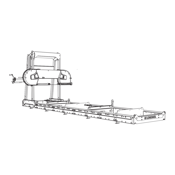
USER MANUAL
ORIGINAL USER MANUAL.
SKU: 0458-395-5431
REV: 1
15 HP PETROL ENGINE
This manual describes installation of the petrol engine for
information on assembly, settings and safety instructions.
Read through the user manual carefully and make sure
you understand its contents before using the saw.
LONCIN
the Logosol band sawmill.
Please see the user manual for your band sawmill for
EN
EN
Advertisement

Related Manuals for Logosol Loncin


Summary of Contents for Logosol Loncin
- Page 1 15 HP PETROL ENGINE LONCIN This manual describes installation of the petrol engine for the Logosol band sawmill. Please see the user manual for your band sawmill for information on assembly, settings and safety instructions. Read through the user manual carefully and make sure...
- Page 2 Accessory pack, 15 hp Loncin Loncin FINAL SAW HEAD ASSEMBLY, 15 HP LONCIN Read through all the set-up instructions before starting to set up, then follow the instructions step by step as you work. Numbering for installation sequence After assembly, follow the instructions under Setup sequence in the sawmill manual...
- Page 3 15 HP PETROL ENGINE Smart set These assembly operations (1–2) must not be performed if the machine is to be fitted with Smart Set (see Smart Set manual). Go to step 3. Fit the handle on the handle tube. M6x50 M5x50 1 x –...
- Page 4 Follow the assembly instructions, then run through the setup sequence for the machine when assembly is complete. 4 x – M10x40 4 x – M10 4 x – SKB 11x3,5x2 Top view: B751 / B751 PRO, 15 hp Loncin...
- Page 5 15 HP PETROL ENGINE Trä på drivremmen runt det drivande hjulet och över spännaren. 1 x – 9020-011-0091 1 x – 9021-014-0003 1 x – 3/8UNFx32 1 x – SRKB 11x35x2 4 x – 03-02448 1 x – 03-02053 Fitting the throttle cable: Start by removing the airbox filter and the lower part of the airbox.
- Page 6 WARNING! Risk of serious injury. WARNING! Risk of burn injuries. The engine and its silencer become very hot during operation and after the engine has been Before adjusting the throttle cable tension on shut down. the engine: Turn the ignition to OFF and close the fuel valve.
- Page 7 15 HP PETROL ENGINE WARNING! Risk of serious injury. WARNING! Risk of burn injuries. The engine and its silencer become very hot during operation and after the engine has been shut down. The hinge switch for the machine has to be fitted before commissioning the machine.
- Page 8 1. Connect the safety switch. The plug must be connected to the severable connector emerging out of the cable assembly. 2. Then plug in the lengthening joint and connect the switch. Then, couple the ring cable lug to the engine chassis. Safety switch SAFETY SWITCH WIRING DIAGRAM 60-SH-6-FAS-2...
-
Page 9: Setup Sequence
Well done! Now you have finished installing the engine, go back to the manual for your band sawmill and carry on with the setup sequence, starting at the point as indicated in the instructions below. SETUP SEQUENCE Read through all the set-up instructions before starting to set up, then follow the instructions step by step as you work. - Page 12 Fiskaregatan 2, SE-871 33 Härnösand, Sweden 0611-182 85 | info@logosol.se | www.logosol.se...
Need help?
Do you have a question about the Loncin and is the answer not in the manual?
Questions and answers