Table of Contents
Advertisement
Quick Links
Advertisement
Table of Contents

Subscribe to Our Youtube Channel
Related Manuals for Optimus IF-8P4ETH/0


Summary of Contents for Optimus IF-8P4ETH/0
- Page 2 IP audio interface IF-8P4ETH/0 for 4 amplifier modules 4ETH SAFETY INSTRUCTIONS IMPORTANT: Read the safety instructions carefully. Keep this manual for future reference. Unplug the equipment during thunderstorms and when it will not be used for a long period of time.
-
Page 3: Table Of Contents
6.5. Output contacts OUTPUT CT 1A, 1B, 2A, 2B, 3A y 3B ................19 6.6. FAIL contacts ............................19 6.7. CAN bus .............................. 20 6.7.1. CAN bus connection between IF-8P4ETH/0 and slave units IF-8P4/0E ........21 6.7.2. Audio connection between IF-8P4ETH/0 and IF-8P4/0E slave units (requires optional IF-PLINK module) ............................. 21 6.7.3. - Page 4 4 amplifier modules 4ETH EQUIPMENT START-UP ......................... 31 8.1. Configuration of the IF-8P4ETH/0 network addresses ................. 33 DISPLAY AND FRONT PANEL OPERATIONS ..................... 35 9.1. Menu structure ........................... 35 9.2. Operations from the front controls of IF-8P4ETH ................36 9.2.1.
-
Page 5: Introduction
Each amplifier incorporates short-circuit/overload protection on the speaker line, as well as thermal protection to prevent failure due to overheating. Optionally, the IF-8P4ETH/0 can have 4 analog audio inputs by incorporating the IF-PIA4 module, and 10 input contacts and 4 output contacts by incorporating the IF-PCT module. - Page 6 IP audio interface IF-8P4ETH/0 for 4 amplifier modules 4ETH Main characteristics: Dual Ethernet connection for installations with redundant Configuration of the IP address in Flash memory, through network systems. The connection is constantly monitored software. and switches automatically if necessary.
-
Page 7: Front View
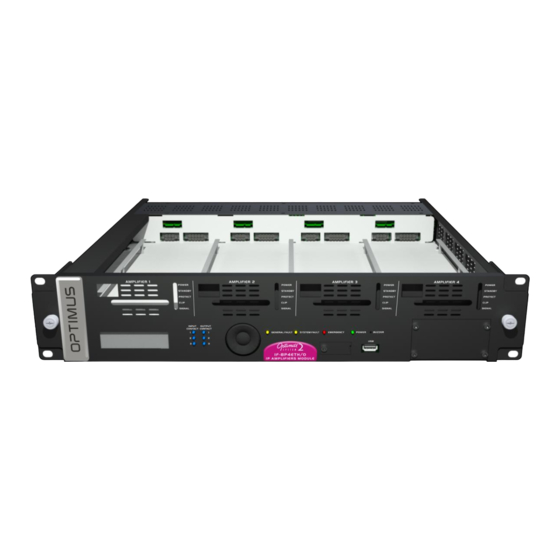
IP audio interface IF-8P4ETH/0 for 4 amplifier modules 4ETH 2. FRONT VIEW Figure 1 1. Slot 1 for modular amplifier (amplifier not included). 12. LED indicators of activated output contacts. 2. Slot 2 for modular amplifier (amplifier not included). 13. Navigation and OK/CANCEL selection keys. -
Page 8: Back View
6.5). 18. Battery compartment (see section 4). 6. CAN BUS (see section 6.7). Data communication bus between IF-8P4ETH/0 and CAN peripherals (NS-CAN), or 19. 24VDC power supply fuse of amplifier 4 (see section 7). between IF-8P4ETH/0 and IF-8P4/0E slave units. -
Page 9: Placement Of The Battery
IP audio interface IF-8P4ETH/0 for 4 amplifier modules 4ETH 4. PLACEMENT OF THE BATTERY From the PA Manager software it is possible to create message time schedules and volume time schedules, and send these schedules to the equipment. In this way, a server PC is not necessary to activate the time schedules, but the equipment activates them automatically. -
Page 10: Insertion And Removal Of Amplifier Modules
IP audio interface IF-8P4ETH/0 for 4 amplifier modules 4ETH 5. INSERTION AND REMOVAL OF AMPLIFIER MODULES 5.1. Inserting the amplifier module 1. Remove the faceplate. Figure 4 2. Remove the front panel from the corresponding slot. Figure 5 Slot 4... - Page 11 Figure 6 4. Push the amplifier module between the two guides to the bottom of the slot, connecting it to the IF-8P4ETH/0. Figure 7 R + D Department IF-8P4ETH version 6.0.001 ENG...
- Page 12 IF-8P4ETH/0 for 4 amplifier modules 4ETH 5. Rest the front of the amplifier module on the IF-8P4ETH/0 chassis. If the module is properly inserted, it should fit with the inside of the input step. Figure 8 5. Slide the moving mechanism of the amplifier faceplate to the left until it locks into the hotswap screw. Fix the amplifier module by means of the hotswap screw.
-
Page 13: Removal Of The Amplifier Module
6. Finally, place and reattach the faceplate. Figure 10 5.2. Removal of the amplifier module 1. After removing the faceplate from the IF-8P4ETH/0, loosen the front retaining screw on the amplifier module you wish to remove as much as possible. - Page 14 Figure 12 3. Holding the amplifier module from the front handle, tilt the amplifier up slightly and pull it out of the IF-8P4ETH/0. Figure 13 Caution: Before replacing the faceplate, the front screw must be tightened to the guide as far as possible.
-
Page 15: Connections
IP audio interface IF-8P4ETH/0 for 4 amplifier modules 4ETH 6. CONNECTIONS 6.1. Connection IP Use the ETH A port (RJ45 connector) and Cat 5e FTP cable to connect the equipment to the IP network. Figure 14 Connection to Ethernet switch 6.2. -
Page 16: Connection Of Loudspeaker Lines
The IF-8P4ETH/0 allows monitoring the status of the loudspeaker lines and determining their status (open line, short circuit, low impedance, high impedance or line in good condition). If a line fault is detected, it automatically disconnects from the corresponding amplifier, while notifying the system of this occurrence. -
Page 17: Example Of Connection Of Loudspeaker Lines To 3 Zone Amplifiers And A Backup Amplifier
IP audio interface IF-8P4ETH/0 for 4 amplifier modules 4ETH 6.3.2. Example of connection of loudspeaker lines to 3 zone amplifiers and a backup amplifier Figure 18 BACKUP ZONE 3 ZONE 2 ZONE 1 AMPLIFIER AMPLIFIER AMPLIFIER AMPLIFIER IF-7P4ETH/0 ATTENTION: The backup amplifier must be of a power rating equal to or greater than the power rating of the largest of the amplifiers to be replaced. -
Page 18: Example Of Connection Of Loudspeaker Lines With Zones A/B
IP audio interface IF-8P4ETH/0 for 4 amplifier modules 4ETH 6.3.3. Example of connection of loudspeaker lines with zones A/B This connection allows redundant loudspeaker lines for the IF-7P4ETH/0 same zone. The rated power of the amplifier is split between both line outputs. -
Page 19: Input Contacts Input Ct 1, 2 And 3
IP audio interface IF-8P4ETH/0 for 4 amplifier modules 4ETH 6.4. Input contacts INPUT CT 1, 2 and 3 Figure 20 INPUT CONTACT CONNECTION WITHOUT SURVEILLANCE The unit has 3 input contacts (INPUT CT 1, 2 and 3). Functionality and idle status (NC/NO) are configured through the PA Manager software. -
Page 20: Can Bus
IF-8P4ETH/0. For this reason, to communicate with the MD-30C, ME-200C and NS-CAN peripherals, the baud rate of the IF-8P4ETH/0 must be set to 33.333 kbit/s, as explained in section 8. -
Page 21: Can Bus Connection Between If-8P4Eth/0 And Slave Units If-8P4/0E
CAN bus connection between IF-8P4ETH/0 and slave units IF-8P4/0E The capacity of each IF-8P4ETH/0 (4 modular amplifiers) can be expanded by adding IF-8P4/0E slave units to the installation, with a capacity of 4 amplifiers per slave. Each IF-8P4ETH/0 can control up to 10 IF-8P4/0E slave units, communicating via CAN bus. -
Page 22: Connecting Ns-Can Noise Sensors To If-8P4Eth/0
For CAN bus connection, the use of a twisted-pair, shielded AWG24 cable is recommended. Attention: The communication speed of the NS-CAN noise sensors is 33.333 kbit/s. Set the speed of the IF-8P4ETH/0 to 33.333 kbit/s to communicate with the NS-CANs (see Section 8. EQUIPMENT START-UP). -
Page 23: Connection Of Can Desks (Md-30C And Me-200C) With Voice Alarm* Functionality
(*) VOICE ALARM allows the desk to access the emergency channel if the CAN communication fails. Any alarm triggered from the desk will be broadcast to all zones with the highest priority. ATTENTION: ONLY IF THE IF-8P4ETH/0 IS INCORPORATED WITH THE OPTIONAL IF-PIA4 MODULE. (ANALOG AUDIO LOCAL INPUTS) The communication speed of the NS-CAN noise sensors is 33.333 kbit/s. -
Page 24: Connection Of Analog Microphone Desks To If-8P4Eth/0 (Md-18, Md-15)
The IF-8P4ETH/0 will reproduce the signal applied to this input by connecting the PRI (priority) contact to the GND (ground) contact. It also has an ACK (Acknowledge) output contact. When this contact is closed, the IF-8P4ETH/0 indicates to the desk that the priority channel is activated and ready to receive audio. -
Page 25: Connection Of A Monaural Music Source
6.10. Connection of the optional additional input and output contact module IF-PCT (10 input contacts and 4 output contacts). Figure 33 The IF-PCT add-on module must be placed in expansion slot 1 of the IF-8P4ETH/0. IF-PCT Module Figure 34 6.10.1. Input contacts 1 to 10... -
Page 26: Output Contacts 1A, 1B, 2A, 2B, 3A , 3B, 4A And 4B
IP audio interface IF-8P4ETH/0 for 4 amplifier modules 4ETH 6.10.2. Output contacts 1A, 1B, 2A, 2B, 3A , 3B, 4A and 4B Figure 37 The IF-PCT module has four output contacts. Each contact CONNECTION OF OUTPUT CONTACTS consists of two terminals (A and B) that can be configured by... -
Page 27: Connection To The Power Grid
IP audio interface IF-8P4ETH/0 for 4 amplifier modules 4ETH 6.11. Connection to the power grid The equipment has a 100-240Vac 50/60 Hz power supply input, through an IEC C20 input, which allows the connection of the equipment to the mains by means of the two-meter cable supplied (CEE 7/7 to IEC 60320 C19 cable). -
Page 28: 24Vdc Secondary Power Supply (Only With Mp-Wdc Series Amplifiers)
6.12. 24VDC secondary power supply (only with MP-WDC series amplifiers) When using MP-WDC series amplifiers, the IF-8P4ETH/0 has 4 independent 24VDC secondary power inputs, one for each amplifier module. This allows these devices to be used in security installations by connecting to a 24VDC battery system. In this case, it will also be necessary to power the control module at 24VDC. -
Page 29: Front Usb Connector: Music Playback From An External Memory Stick
IP audio interface IF-8P4ETH/0 for 4 amplifier modules 4ETH 6.13. Front USB connector: Music playback from an external memory stick The unit has a USB 2.0 port on the front panel for use as a music program input. To do this, connect an external memory stick containing audio files in MP3, WAV or OGG format to this port. -
Page 30: Fuse Placement Of The Amplifier Module In Mp-Wdc Amplifiers
IP audio interface IF-8P4ETH/0 for 4 amplifier modules 4ETH 7. FUSE PLACEMENT OF THE AMPLIFIER MODULE IN MP-WDC AMPLIFIERS In the MP-WDC series amplifiers, the 24VDC secondary power input is protected by a blade- DC FUSE AMPLIFIER type fuse. For each MP-WDC series amplifier module, a corresponding fuse is supplied. -
Page 31: Equipment Start-Up
The commissioning of the unit requires the sending of configurations to the unit via the Ethernet connection. This requires a PC equipped with a network card and connected to the IF-8P4ETH/0, either via a switch or directly via a network cable. The PC must have the PA Manager software or the PA Manager Configurator software installed. - Page 32 Name of the area Zone number Configuration of Backup options Connect the devices (IF-8P4ETH/0 and amplifier modules) to the system structure. To do this, right-click on these devices and select the Connect option from the pop-up menu. Connection of the amplifier module...
-
Page 33: Configuration Of The If-8P4Eth/0 Network Addresses
4 amplifier modules 4ETH 5. Save the changes to the installation (menu File > Save). 6. Send configurations to the IF-8P4ETH/0 device. Right-click on the device name and select the Send configurations option from the pop-up menu. ATTENTION In order to be able to send configurations to the equipment, it is necessary that the equipment and the PC are within the same IP address range. - Page 34 IP audio interface IF-8P4ETH/0 for 4 amplifier modules 4ETH 3. Click on Network. 4. Modify desired network settings (IP, Netmask Gateway) and click on the Change Network Settings button apply the changes. equipment will restart automatically. R + D Department...
-
Page 35: Display And Front Panel Operations
IP audio interface IF-8P4ETH/0 for 4 amplifier modules 4ETH 9. DISPLAY AND FRONT PANEL OPERATIONS Figure 45 In standby mode the display shows the following information: Scrolling between menu items (previous item) Figure 44 Applies the Equipment name selected option... -
Page 36: Operations From The Front Controls Of If-8P4Eth
IP audio interface IF-8P4ETH/0 for 4 amplifier modules 4ETH 9.2. Operations from the front controls of IF-8P4ETH 9.2.1. Check the firmware version of the 9.2.4. Cancellation of alarms equipment 1. Press ► to display the menu. 1. Press ► to display the menu. -
Page 37: Technical Characteristics
IP audio interface IF-8P4ETH/0 for 4 amplifier modules 4ETH 11. TECHNICAL CHARACTERISTICS 2 Ethernet connections (RJ45) A and B for redundant installations. IP Layer 3 & Layer 4 Ethernet communication Network. CAN bus Speed: 500kbit/s or 33.3kbit/s SIP protocol RFC3261. -
Page 38: Mp-Wd1 Series Modular Amplifiers
IP audio interface IF-8P4ETH/0 for 4 amplifier modules 4ETH 12. MP-WD1 SERIES MODULAR AMPLIFIERS Class D modular amplifiers. High efficiency (90%). Hot-swappable. Various power ratings available (120, 150, 250, 300 and 460 watts). MP-120WD1 MP-300WD1 MP-150WD1 MP-460WD1 MP-250WD1 POWER indicator light. Power indicator of the amplifier module. -
Page 39: Mp-Wdc Series Modular Amplifiers
IP audio interface IF-8P4ETH/0 for 4 amplifier modules 4ETH 13. MP-WDC SERIES MODULAR AMPLIFIERS Class D modular amplifiers. High efficiency (90%). Hot-swappable. Various power ratings available (60, 120, 150, 250, 300 and 460 watts). MP-60WDC MP-120WDC MP-300WDC MP-150WDC MP-460WDC MP-250WDC POWER indicator light. -
Page 40: Network Specifications On Optimax 2 Systems
IP audio interface IF-8P4ETH/0 for 4 amplifier modules 4ETH 14. NETWORK SPECIFICATIONS ON OPTIMAX 2 SYSTEMS The OPTIMAX 2 public address system allow audio and control data communication over Ethernet and IP networks. Working at OSI levels 3 and 4, the protocol allows communication through routers (IP protocol) by means of gateway and subnet mask configurations. - Page 41 IP audio interface IF-8P4ETH/0 for 4 amplifier modules 4ETH For operation with OPTIMAX 2 protocol, the following parameters must be fulfilled: Protocol Multicast address Port Others Control TCP (Unicast) 10102,10103,10104 Unicast Audio (point UDP (Unicast) Between 6000 and 32000 Selected by configs.
- Page 42 IP audio interface IF-8P4ETH/0 for 4 amplifier modules 4ETH Backbone network specifications Bandwidth: 3kbps of control data for each equipment and 1kbps additionally for each alarm. Example: Matrix with 5 alarms 3kbps (data) + (5 alarms * 1kbps) = 8kbps Paging console with 2 alarms ...
- Page 43 IP audio interface IF-8P4ETH/0 for 4 amplifier modules 4ETH Network protocol stack (*) Multicast addresses and reserved ports R + D Department IF-8P4ETH version 6.0.001 ENG...
-
Page 44: Software And Firmware Versions
IF-8P4ETH/0 for 4 amplifier modules 4ETH 15. SOFTWARE AND FIRMWARE VERSIONS The functionalities described in this user manual are valid for software and firmware versions equal to or higher than: IF-8P4ETH/0 Firmware Application version 6.0.27 Linux version 5.4.84 PA Manager software Version 6.0.27... -
Page 45: Warranty
In the event that the guarantee rights do not In order to claim the guarantee rights, it shall be an essential requirement to apply, OPTIMUS S.A. shall duly inform the client. If, within a period of 6 weeks present the original purchase invoice or the guarantee certificate.
Need help?
Do you have a question about the IF-8P4ETH/0 and is the answer not in the manual?
Questions and answers