Table of Contents
Advertisement
Available languages
Available languages
Quick Links
Advertisement
Chapters
Table of Contents

Subscribe to Our Youtube Channel
Related Manuals for Optimus IF-7P4ETH/0


Summary of Contents for Optimus IF-7P4ETH/0
-
Page 4: Table Of Contents
Connection of peripherals NS-CAN to the IF-7P4ETH/0 ............14 5.8.2. CAN Bus connection between the IF-7P7ETH/0 and the IF-7P4/0E slave units ...... 15 5.9. Connection between the IF-7P4ETH/0 and the IF-7P4/0E slave units using the IF-PLINK expansion module (not included) ..........................15 5.10. - Page 5 IP Audio Interface IF-7P4ETH/0 with 4 slot for power amplifier modules allocate 4 amplifiers 4ETH 8.2.6. Modify the volume of the zones ..................... 24 8.2.7. Mute a zone ..........................24 8.2.8. Disable a zone ......................... 24 SYSTEM ALARMS ..........................24 10.
-
Page 6: Introduction
IP Audio Interface IF-7P4ETH/0 with 4 slot for power amplifier modules allocate 4 amplifiers 4ETH 1. INTRODUCTION Audio interface with IP connection for COMPACT system. It has four slots that allow to insert module amplifiers from MP-WD1* series (not included) and four local analog inputs (program /priority) of configurable sensitivity. -
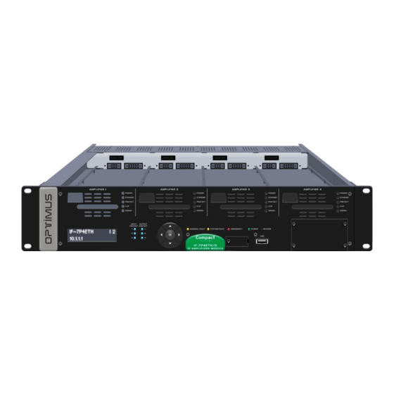
Page 7: Front View
IP Audio Interface IF-7P4ETH/0 with 4 slot for power amplifier modules allocate 4 amplifiers 4ETH 2. FRONT VIEW Figure 1 1. Slot 1 for amplifier module (amplifier not included). 13. Navigation keys and OK/CANCEL selection. 2. Slot 2 for amplifier module (amplifier not included). -
Page 8: Rear View
IP Audio Interface IF-7P4ETH/0 with 4 slot for power amplifier modules allocate 4 amplifiers 4ETH 3. REAR VIEW Figure 2 1. Surety paging options module space (not included). 2. Speakers line output connection for CHANNEL 4 (lines 4A and 4B*) and 100V input of the BACKUP 4 amplifier. -
Page 9: Control Module
Speed of the network. If the LED is lit, indicates a speed CAN Contacts of 100 Mbps. If unlit, indicates a network speed of 10 Data communication bus between the IF-7P4ETH/0 and Mbps (it is highly recommended to use a transmission the system peripherals (NS-CAN), or between the speed of 100 Mbps). -
Page 10: Placement Of The Battery
IP Audio Interface IF-7P4ETH/0 with 4 slot for power amplifier modules allocate 4 amplifiers 4ETH 4. PLACEMENT OF THE BATTERY From the Call Point software it is possible to create message time schedules and volume time schedules, and send these schedules to the equipment. -
Page 11: Connection
IP Audio Interface IF-7P4ETH/0 with 4 slot for power amplifier modules allocate 4 amplifiers 4ETH 5. CONNECTION 5.1. IP Connection Figure 6 Connection to the Ethernet switch 5.2. Connection in installations with a redundant Ethernet network Figure 7 Connection to the Ethernet... -
Page 12: Speakers Connection
IP Audio Interface IF-7P4ETH/0 with 4 slot for power amplifier modules allocate 4 amplifiers 4ETH 5.3. Speakers connection The equipment has four channels (one per amplifier) for the connection of 100V high impedance speaker lines. Each channel has connections for A / B lines for installations with redundant loudspeaker lines (not implemented) and a backup amplifier input. - Page 13 IP Audio Interface IF-7P4ETH/0 with 4 slot for power amplifier modules allocate 4 amplifiers 4ETH Figure 9 SPEAKER LINES CONNECTION 3 ZONE AMPLIFIERS + 1 BACKUP AMPLIFIER BACKUP ZONE ZONE ZONE AMPLIFIER AMPLIFIER AMPLIFIER AMPLIFIER IF-7P4ETH/0 WARNING: The sum of the power ratings of the loudspeakers connected to output of an amplifier must not exceed the power of the amplifier module.
-
Page 14: Local Audio Inputs
IP Audio Interface IF-7P4ETH/0 with 4 slot for power amplifier modules allocate 4 amplifiers 4ETH 5.4. Local Audio Inputs Figure 10 Each of the inputs corresponds to a channel (CHANNELS 1, 2, 3 and 4), and each channel corresponds to an amplifier. In this way,... -
Page 15: Power Supply
IP Audio Interface IF-7P4ETH/0 with 4 slot for power amplifier modules allocate 4 amplifiers 4ETH Figure 12 Figure 13 Balanced audio connection Unbalanced audio connection to a local audio input of the IF-7P4ETH / 0 to a local audio input of the IF-7P4ETH / 0... -
Page 16: Input Contacts
4 slot for power amplifier modules allocate 4 amplifiers 4ETH 5.6. Input contacts The IF-7P4ETH/0 incorporates three input contacts (INPUT CT 1, 2 and 3). If you wish, the system may monitor these contacts (short-circuit or open line detection). Figure 15 Figure 16... -
Page 17: Can Bus Connection Between The If-7P7Eth/0 And The If-7P4/0E Slave Units
4ETH 5.8.2. CAN Bus connection between the IF-7P7ETH/0 and the IF-7P4/0E slave units The capacity of each IF-7P4ETH/0 (4 modular amplifiers) can be expanded by adding to the installation IF-7P4/0E slave units, with the capacity of 4 amplifiers per slave. -
Page 18: Front Usb Connector: Playing Music From An External Memory
IP Audio Interface IF-7P4ETH/0 with 4 slot for power amplifier modules allocate 4 amplifiers 4ETH 5.10. Front USB connector: Playing music from an external memory The unit has a USB 2.0 port on the front panel for use as a musical program input. To do this, connect to this port an external memory that contains audio files in MP3, WAV or OGG format. - Page 19 IP Audio Interface IF-7P4ETH/0 with 4 slot for power amplifier modules allocate 4 amplifiers 4ETH 2. If you want to use slots 2, 3 or 4, remove the corresponding slot panel. Figure 23 3. Insert the amplifier module by fitting it into the slot guides.
- Page 20 IP Audio Interface IF-7P4ETH/0 with 4 slot for power amplifier modules allocate 4 amplifiers 4ETH 3. Fasten the amplifier module by means of the hot-swapping screw. Figure 25 4. Finally, fix the front plate. Figure 26 R + D Department...
-
Page 21: Commissioning The Unit
4 slot for power amplifier modules allocate 4 amplifiers 4ETH 7. COMMISSIONING THE UNIT Display language and buzzer configuration. To commission the IF-7P4ETH/0 we must send Contacts configuration. configurations Ethernet Emergency mode configuration. connection. Accomplishing this requires a PC SIP Calls configuration. - Page 22 Connect. 5. Open the File menu and select Save. 6. Send the settings to the IF-7P4ETH/0 unit. In the structure of the installation, right click with the mouse on the equipment and select the option Send configurations.
-
Page 23: Configuration Of The If-7P4Eth/0 Network Addresses
4 amplifiers 4ETH 7.1. Configuration of the IF-7P4ETH/0 network addresses To change the unit's network settings by default, carry out the following: 1. From the PC, open a browser, enter the IP address for the unit and press INTRO. By default the IP address is 10.1.1.1. Warning: The range of IP addresses for the unit and the PC must match. -
Page 24: Configuration Of The Can Bus Communication Speed
7.2. Configuration of the CAN bus communication speed The IF-7P4ETH/0 communicates with the slave units (IF-7P4/0E) at a transmission rate of 500 kbit/s. This is the speed set by default. If the installation does not have IF-7P4/0E slave units but does have CAN peripherals (NS-CAN...) whose transmission speed is 33.3kbit/s, it is necessary to change the communication speed of the IF-7P4ETH/0. -
Page 25: Display And Front Panel Operation
Enter the selec- level menu ted menu Open audio channels Using the navigation buttons you can access the different menus of the IF-7P4ETH/0. Move between options in a menu (next item) 8.1. Structure of the menus R + D Department... -
Page 26: Operations From The Front Pannel
IP Audio Interface IF-7P4ETH/0 with 4 slot for power amplifier modules allocate 4 amplifiers 4ETH 8.2. Operations from the front pannel 8.2.1. Check the firmware version 8.2.6. Modify the volume of the zones 1. Press ► to view the menu. -
Page 27: Technical Characteristics
IP Audio Interface IF-7P4ETH/0 with 4 slot for power amplifier modules allocate 4 amplifiers 4ETH Acoustic alarm indicator (buzzer): Intermittent buzzing sound. The IF-7P4ETH incorporates a buzzer that generates an acoustic signal each time an alarm is received. The acoustic indication is a buzzing sound that lasts 10 seconds and is periodically repeated every 20 seconds. -
Page 28: Modular Amplifiers Mp-Wd1 Series
IP Audio Interface IF-7P4ETH/0 with 4 slot for power amplifier modules allocate 4 amplifiers 4ETH 11. MODULAR AMPLIFIERS MP-WD1 SERIES Class D amplifiers. High efficiency (90%). Hot swap. Several power available (120, 150, 250, 300 & 460 Watts). MP-120WD1 MP-300WD1... -
Page 29: Compact System Network Specifications
IP Audio Interface IF-7P4ETH/0 with 4 slot for power amplifier modules allocate 4 amplifiers 4ETH 12. COMPACT SYSTEM NETWORK SPECIFICATIONS COMPACT public address system supports audio and control data Communications through Ethernet and IP. Since it works on levels 3 and 4 of the OSI scale, COMPACT protocol supports Communications through routers (IP protocol) by means of the configurations of the gateways and subnetwork masks. - Page 30 IP Audio Interface IF-7P4ETH/0 with 4 slot for power amplifier modules allocate 4 amplifiers 4ETH For operating with COMPACT protocol, the following parameters must be met: Protocol Multicast address Port Others Control TCP (Unicast) 10102,10103,10104 Unicast Audio (point UDP (Unicast) Between 6000 and 32000 Selected by configurations.
- Page 31 IP Audio Interface IF-7P4ETH/0 with 4 slot for power amplifier modules allocate 4 amplifiers 4ETH Backbone network specifications Bandwidth: 3kbps of control data for each equipment and 1kbps additionally for each alarm. Example: Matrix with 5 alarms 3kbps (data) + (5 alarms * 1kbps) = 8kbps Paging console with 2 alarms ...
-
Page 32: Software And Firmware Versions
Call Point software Version 5.0.8540 Optimax flasher tool Version .8046 14. DOCUMENT VERSION TRACKING Reference system Type of Document Confidentiality COMPACT / IF-7P4ETH/0 Installation and operation guide Date Modifications Content Written by: 3.2.001 September 2019 R+D Department Section 3.1. The detection time of the activation pulse of the input contacts can be configured. -
Page 33: Guarantee
In the event that the guarantee rights do not apply, OPTIMUS S.A. shall duly inform the client. If, within a period of 6 weeks 2. GUARANTEE PROVISIONS... - Page 36 5.8.1. Conexión de periféricos NS-CAN al IF-7P4ETH/0 ..............14 5.8.2. Conexión del bus CAN entre IF-7P4ETH/0 y unidades esclavas IF-7P4/0E ......15 5.9. Conexión entre el IF-7P4ETH/0 y las unidades esclavas IF-7P4/0E mediante el módulo de expansión IF-PLINK (no incluido) ..........................15 5.10.
- Page 37 Interfaz de audio IP IF-7P4ETH/0 para 4 módulos amplificadores 4ETH 8.2.6. Modificar el volumen de las zonas ..................24 8.2.7. Silenciar una zona ........................24 8.2.8. Deshabilitar una zona ......................24 ALARMAS DEL SISTEMA ........................24 10. CARACTERÍSTICAS TÉCNICAS ......................... 25 11.
-
Page 38: Introducción
Interfaz de audio IP IF-7P4ETH/0 para 4 módulos amplificadores 4ETH 1. INTRODUCCIÓN Interfaz de audio con conexión a IP para sistemas COMPACT. Dispone de cuatro slots que permiten alojar amplificadores de la serie MP-WD1* (amplificadores no incluidos) y cuatro entradas de audio locales analógicas, de programa/prioridad y sensibilidad configurable. -
Page 39: Vista Frontal
Interfaz de audio IP IF-7P4ETH/0 para 4 módulos amplificadores 4ETH 2. VISTA FRONTAL Figura 1 12. Indicadores luminosos de contacto de salida activado. 1. Slot 1 para amplificador modular (amplificador no inclui- do). 13. Teclas de navegación y selección OK/CANCEL. -
Page 40: Vista Posterior
Interfaz de audio IP IF-7P4ETH/0 para 4 módulos amplificadores 4ETH 3. VISTA POSTERIOR Figura 2 1. Espacio para el módulo de seguridad de avisos (no incluido). 2. Conexión de la línea de altavoces del canal 4 (líneas 4A y 4B*) y entrada de 100V del amplificador de respaldo para el canal 4. -
Page 41: Módulo De Control
Velocidad de la red. Encendido indica una velocidad de Contactos BUS 100Mbps. Apagado indica una velocidad de red de Bus de comunicación de datos entre el IF-7P4ETH/0 y los 10Mbps (es altamente recomendable la utilización de periféricos CAN ( NS-CAN), o entre el IF-7P4ETH/0 y las una velocidad de transmisión de 100 Mbps). -
Page 42: Colocación De La Pila
Interfaz de audio IP IF-7P4ETH/0 para 4 módulos amplificadores 4ETH 4. COLOCACIÓN DE LA PILA Desde el software Call Point es posible crear programaciones horarias de mensajes y programaciones horarias de volumen, y enviar estas programaciones al equipo. De este modo, no es necesario un PC servidor para activar las programaciones horarias, sino que es el equipo quien las activa automáticamente. -
Page 43: Conexión
Interfaz de audio IP IF-7P4ETH/0 para 4 módulos amplificadores 4ETH 5. CONEXIÓN 5.1. Conexión IP Figure 6 Conexión al switch Ethernet 5.2. Conexión en instalaciones con red ethernet redundante Figure 7 Conexión Ethernet al switch 2 Conexión Ethernet al switch 1 R + D Department IF-7P4ETH versión 5.0.002 ESP... -
Page 44: Conexión De Las Líneas De Altavoces
Interfaz de audio IP IF-7P4ETH/0 para 4 módulos amplificadores 4ETH 5.3. Conexión de las líneas de altavoces El equipo dispone de cuatro canales (uno por amplificador) para la conexión de líneas de altavoces de alta impedancia de 100V. Cada canal dispone de conexiones para líneas A/B para instalaciones con líneas de altavoces redundantes (no implementado) y de una entrada de amplificador de reserva. - Page 45 Interfaz de audio IP IF-7P4ETH/0 para 4 módulos amplificadores 4ETH Figura 9 CONEXIÓN DE LÍNEAS DE ALTAVOCES, 3 AMPLIFICADORES DE ZONA + 1 AMPLIFICADOR DE RESPALDO AMPLIFICADOR AMPLIFICADOR AMPLIFICADOR AMPLIFICADOR DE ZONA DE ZONA DE RESPALDO DE ZONA IF-7P4ETH/0 ATENCIÓN: ...
-
Page 46: Entradas De Audio Locales
Interfaz de audio IP IF-7P4ETH/0 para 4 módulos amplificadores 4ETH 5.4. Entradas de audio locales Figura 10 Cada una de las entradas corresponde a un canal (CHANNEL 1, 2, 3 y 4), y cada canal corresponde a un amplificador. De este modo,... -
Page 47: Alimentación
4ETH Figura 12 Figura 13 Conexión de una señal balanceada Conexión de una señal no balanceada a una entrada de audio local del IF-7P4ETH/0 a una entrada de audio local del IF-7P4ETH/0 Equipo externo Equipo externo AUDIO – AUDIO +... -
Page 48: Contactos De Entrada
Cada contracto dispone de dos terminales (A y B). 5.8. Conexión del BUS CAN Para la conexión del bus CAN se recomienda la utilización de un cable de par trenzado y apantallado AWG24. 5.8.1. Conexión de periféricos NS-CAN al IF-7P4ETH/0 Atención: La velocidad de comunicación de Figura 18 fábrica del equipo IF-7P4ETH/0 es de 500... -
Page 49: Conexión Del Bus Can Entre If-7P4Eth/0 Y Unidades Esclavas If-7P4/0E
4ETH 5.8.2. Conexión del bus CAN entre IF-7P4ETH/0 y unidades esclavas IF-7P4/0E La capacidad de cada IF-7P4ETH/0 (4 amplificadores modulares) puede ampliarse añadiendo a la instalación unidades esclavas IF- 7P4/0E, con capacidad de 4 amplificadores por esclava. Cada IF-7P4ETH/0 puede controlar... -
Page 50: Conector Usb Frontal: Reproducción De Música Desde Una Memoria Externa
Interfaz de audio IP IF-7P4ETH/0 para 4 módulos amplificadores 4ETH 5.10. Conector USB frontal: Reproducción de música desde una memoria externa El equipo dispone de un puerto USB 2.0 en el panel frontal para utilizarse como entrada de programa musical. Para ello, conecte a este puerto una memoria externa que contenga archivos de audio en formato MP3, WAV o OGG. - Page 51 Interfaz de audio IP IF-7P4ETH/0 para 4 módulos amplificadores 4ETH 2. Si desea utilizar los slots 2, 3 o 4, retire el panel del slot correspondiente. Figura 23 3. Inserte el módulo amplificador entre las guías del slot. Figura 24 R + D Department IF-7P4ETH versión 5.0.002 ESP...
- Page 52 Interfaz de audio IP IF-7P4ETH/0 para 4 módulos amplificadores 4ETH 3. Fije el módulo amplificador por medio del tornillo hotswap (intercambio en caliente). Figura 25 4. Finalmente, fije la placa frontal. Figura 26 R + D Department IF-7P4ETH versión 5.0.002 ESP...
-
Page 53: Puesta En Marcha Del Equipo
Ethernet. Para ello, es necesario Configuración de las llamadas SIP. un PC equipado con tarjeta de red y conectado al IF-7P4ETH/0, bien a través de un switch, o directamente a través de un cable de red. El PC debe tener instalado el software Nombre del equipo. - Page 54 Conectar del menú emergente. 5. Guarde los cambios en la instalación (menú Archivo > Guardar). 6. Envíe configuraciones al equipo IF-7P4ETH/0. Haga clic con el botón secundario del ratón sobre el nombre del equipo y seleccione la opción Enviar configuraciones del menú...
-
Page 55: Configuración De Las Direcciones De Red Del If-7P4Eth/0
4 módulos amplificadores 4ETH 7.1. Configuración de las direcciones de red del IF-7P4ETH/0 Para cambiar las configuraciones de red por defecto del equipo haga lo siguiente: 1. Desde el PC, abra un navegador, introduzca la dirección IP del equipo y pulse INTRO. Por defecto la dirección IP es 10.1.1.1. -
Page 56: Configuración De La Velocidad De Comunicación Del Bus Can
7.2. Configuración de la velocidad de comunicación del bus CAN El IF-7P4ETH/0 se comunica con las unidades esclavas (IF-7P4/0E) a una velocidad de transmisión de 500 kbit/s. Esta es la velocidad establecida por defecto. Si la instalación no dispone de unidades esclavas IF-7P4/0E pero sí dispone de periféricos CAN (NS-CAN...) cuya velocidad de transmisión es de 33.3kbit/s, es necesario cambiar la velocidad de comunicación del IF-7P4ETH/0. -
Page 57: Display Y Operaciones Desde El Panel Frontal
Interfaz de audio IP IF-7P4ETH/0 para 4 módulos amplificadores 4ETH 8. DISPLAY Y OPERACIONES DESDE EL PANEL FRONTAL Figura 28 En reposo el display muestra la siguiente información: Desplazamiento entre las opciones de un menú (elemento anterior) Figura 27 Aplica la opción... -
Page 58: Operaciones Desde Los Controles Frontales Del If-7P4Eth
Interfaz de audio IP IF-7P4ETH/0 para 4 módulos amplificadores 4ETH 8.2. Operaciones desde los controles frontales del IF-7P4ETH 8.2.1. Comprobar la versión de firmware del equipo 8.2.6. Modificar el volumen de las zonas 1. Pulse ► para ver el menú. -
Page 59: Características Técnicas
Interfaz de audio IP IF-7P4ETH/0 para 4 módulos amplificadores 4ETH Indicador acústico (zumbador) de alarma: Pitido intermitente. El equipo dispone de un zumbador que genera una indicación acústica cada vez que recibe una alarma. La indicación acústica, un pitido de 10 segundos de duración, se va repitiendo periódi- camente cada 20 segundos. -
Page 60: Amplificadores Modulares De La Serie Mp-Wd1
Interfaz de audio IP IF-7P4ETH/0 para 4 módulos amplificadores 4ETH 11. AMPLIFICADORES MODULARES DE LA SERIE MP-WD1 Amplificadores modulares de clase D. Alta eficiencia (90%). Intercambio en caliente. Varias potencias disponibles (120, 150, 250, 300 y 460 vatios). MP-120WD1 MP-300WD1... -
Page 61: Especificaciones De Red En Sistemas Compact
Interfaz de audio IP IF-7P4ETH/0 para 4 módulos amplificadores 4ETH 12. ESPECIFICACIONES DE RED EN SISTEMAS COMPACT El sistema de megafonía COMPACT permite la comunicación de audio y datos de control a través de redes Ethernet e IP. Al trabajar en niveles 3 y 4 de la escala OSI, el protocolo COMPACT permite la comunicación a través de routers (protocolo IP) me- diante las configuraciones de las puertas de enlace y máscaras de subred. - Page 62 Interfaz de audio IP IF-7P4ETH/0 para 4 módulos amplificadores 4ETH Para el funcionamiento con protocolo COMPACT se precisa cumplir los siguientes parámetros: Protocolo Dirección Multicast Puerto Otros Control TCP (Unicast) 10102, 10103,10104 Audio Unicast Seleccionado por UDP (Unicast) Entre 6000 y 32000 (punto a punto) configuraciones.
- Page 63 Interfaz de audio IP IF-7P4ETH/0 para 4 módulos amplificadores 4ETH Especificaciones de la red Local (LAN) Ancho de banda: 3kbps para datos de control por equipo y 1kbps adicional por cada alarma. Ejemplo: Matriz con 5 alarmas 3kbps (datos) + (5 alarmas * 1kbps) = 8kbps Pupitre microfónico con 2 alarmas ...
-
Page 64: Versiones De Software Y Firmware
Call Point software Version 5.0. 8540 Optimax flasher tool Version .8046 14. DOCUMENT VERSION TRACKING Reference system Type of Document Confidentiality COMPACT / IF-7P4ETH/0 Installation and operation guide Date Modifications Content Written by: 3.2.001 Septiembre 2019 R+D Department Apartado 3.1. El tiempo de detección del pulso de activación de los contactos de entrada puede configurarse. -
Page 65: Garantía
Los productos sin derechos de garantía sólo se repararán contra pago de los OPTIMUS S.A. se reserva el derecho de cargar el coste adicional de estos compo- gastos por el cliente. En caso de ausencia de derechos de garantía, OPTIMUS S.A.
Need help?
Do you have a question about the IF-7P4ETH/0 and is the answer not in the manual?
Questions and answers