Table of Contents
Advertisement
Advertisement
Table of Contents

Subscribe to Our Youtube Channel
Related Manuals for Power Acoustik HD-14KIT


Summary of Contents for Power Acoustik HD-14KIT
- Page 1 Owner’s Manual IPx5 4-Channel WATERPROOF Amplifier FACEPLAT E HD-14KIT...
-
Page 2: Table Of Contents
Safety First Contents Safety Definitions Safety First Statements in this manual preceded by following words are of special significance: Pre-Riding Check list Care and cleaning WARNING Screen WARNING indicates a potentially hazardous Appearance situation which, if not avoided, could result Accessories in death or serious injury. -
Page 3: Pre-Riding
Front Android Auto®. 6. Selectstation or media CARE AND CLEANING Use only HD-14KIT recommended products and methods to keep the radio, speakers, and other audio system components clean and in good condition. Do not use any abrasives, polishes, or rubbing compoundsto clean the screen or other components. -
Page 4: Accessories
Accessories Harness Included! Connector to Headunit(ISO A+B) 48 Pin to Motorcycle Installation Trim Ring: Installation Bracket(Left/Right): External Microphone: Installation Bracket Screws TM5*6 (8pcs): Manual: Installation Trim Ring Owner’s Manual Screws TA4*10 (4pcs) : IPx5 WATERPROOF FACEPLAT E HD-14KIT... -
Page 5: Installation
Installation REMOVAL OF ORIGINAL HEAD UNIT Street Glide To prevent accidental vehicle start-up, which could cause death or serious injury, remove main fuse before proceeding. 1. Remove three outer fairing bolts using a T27 Torx screw driver. The three outer fairing bolts are located below the windshield. - Page 6 Installation 5. Disconnect electrical connections to the head unit. 5.1) Remove the main wire harness connector (1). To remove the main wire harness, depress the latch lock with a small flathead screwdriver and swivel the latch aside. Pull the wire harness connector to remove from the socket.
- Page 7 Installation REMOVAL OF ORIGINAL HEAD UNIT Road Glide To prevent accidental vehicle start-up, which could cause death or serious injury, remove main fuse before proceeding. 1. Detach each turn signal / indicator light by 2. Remove four inner fairing bolts using a T25 Torx removing the adjacent allen socket screw, driver.
- Page 8 Installation 8. Disconnect electrical connections to the head unit. 8.1) Remove the main wire harness connector (1). To remove the main wire harness,depress the latch locking tab wiht a small flathead screwdriver. While depressing the locking tab, pull the USB cable to release it from socket.
- Page 9 3. Connect the USB and radio antenna cables disconnected during removal of the OEM headunit to the matching sockets on the back of HD-14KIT. If either are difficulet to connect, verify the oriention of the connector(s) is correct. If any aftermarket audio amplifiers will be used in the audio system, take a moment to connect the RCA cables to the corresponding audio outputs.
- Page 10 4. Insert and lock the male ISO head unit wire harness connector to the female socket of the included wire harness for HD-14KIT. Then, insert and lock the male connector of the HD-14KIT wire harness into the corresponding female socket on the back of HD-14KIT.
- Page 11 7. If an alternative handlebar integration module is available, cut the wires leading to the 12-pin and 14-pin connectors and discard them. Follow the color coded call-out below to connect the wires of HD-14KIT wire harness to the corresponding inputs and outputs of the alternate handlebar control module.
-
Page 12: Headunit Control
Headunit Control HD-14KIT (Volume +) Power / Mute Press to increase the volume value. • When the power is off, press to power • • When the unit is working, short pressing (Volume -) for Mute, press again for unmute. -
Page 13: Main Menu
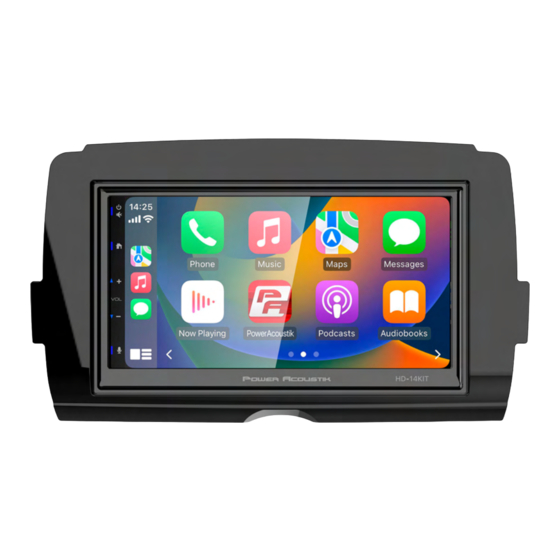
Settings Main Menu Sound Setting HD-14KIT is a headunit for Motorcycle with Below shown is the Sound Setting Menu. the following functions: Apple CarPlay®, Android Auto®, Radio, USB, BT Music, Phone . Touch the corresponding Mode icon to enter playing mode. The Mode icon in gray means the corresponding function is not ready, or the proper device has not been connected. - Page 14 BT Setting: Subwoofer Frequency: 50Hz/80Hz/120Hz /160Hz Subwoofer Level: -10~+10 Default Volume : HD-14KIT Radio Area: Select the region: America/ Europe/ Eastern Europe/ Japan / Southeast Asia /Latin America / Asia / Australia. Set the Main / BT Talking /Navi /Voice default Language: Select the desired language.
-
Page 15: Apple Carplay/Android Auto
Apple CarPlay Android Auto ® ® Apple CarPlay : You can operate iPhone applications with finger gestures such as tapping, dragging, scrolling, or flicking on the screen of this product. Compatible iPhone models For details about compatibility of iPhone models, refer to the following website. https://www.apple.com/ios/carplay Application keys WARNING... -
Page 16: Radio Operation
Android Auto Radio ® Notes on using Android Auto Touch FM1 to select FM1 Band. • Android phone with Android 5.0 or higher is required. Update to the latest OS version Touch AM1 to select AM1 Band. before use. • Your Android phone needs to support Touch to select Band, FM1>FM2 Android Auto. -
Page 17: Usb Operation
Bluetooth Photo Playback Store a Station 1 . Tune radio to desired station. 2. Touch and hold the one of the preset station Press to Rotare the picture for playback. for more than 3 seconds, then the preset button will be highlighted on the screen,and the preset Press to Zoom Out the picture. -
Page 18: Bluetooth Phone
2. Search for Bluetooth devices from phone. You can see the HD-14KIT, select the HD-14KIT for pairing Show the usable devices. and connection. 3. The phone will pop up the pairing code and click BT Setup. - Page 19 Bluetooth Bluetooth 1. Touch the icon to enter below screen. HD-14KIT 2. Using the keypad, touch 0-9,*,#, enter the phone number you wish to dial. If you input an incorrect number, touch the icon on the keypad to delete the incorrect number.
-
Page 20: Trouble Shooting
Trouble Shooting Problem Cause Correct action Check fuse Replace fuse Cannot power on Press RST button on the panel by Other factors causing MPU penpoint, then, power on to malfunciton After ignition switch off, setting Change battery or fuse Reset information and save information are lost Poor performance Move the car to another place,... - Page 21 • Reorient or relocate the receiving antenna. • Increase the separation between the equipment and receiver. • Connect the equipment into an outlet on a circuit different from that to which the receiver is connected. • Consult your Power Acoustik dealer.
-
Page 22: Speci Cation
Specification General Power Supply ................................DC10~16Volts Grounding System............................Negative Ground Current Drain..................................15A(Max.) RMS Power Output...............................4x18w/channel Speaker Impedance............................2- or 4-Ohm Load Frequency Response..............................20Hz~20KHz Operating Temperature .............................-20~+60℃ Dimensions .........................178mm(W)x135mm(D)x103mm(H) TFT Display TFT Screen size....................................7inch Resolution.................................1024x600 pixels FM Radio Frequency Range (USA)............................87.5~107.9MHz Frequency Range (Europe) ..........................87.5~108MHz Usable Sensitivity (S/N=30dB)............................≤15dB S/N Ratio......................................≥55dB Stereo Separation..................................≥30dB... -
Page 23: Warranty
LIMITED ONE-YEAR CONSUMER WARRANTY WITH PURCHASE AND INSTALLATION BY A Power Acoustik AUTHORIZED DEALER Power Acoustik promises to the original purchaser, to repair or replace this product with a new or refurbished unit (at Power Acoustik’s sole and absolute discretion) should it prove to be defec-... - Page 24 Headquarters 1550 South Maple Ave. Montebello CA, 90640 Technical Support: (800) 832-4647. Email: tech-support@poweracoustik.com Copyright © 2023 POWER ACOUSTIK ELECTRONICS...
Need help?
Do you have a question about the HD-14KIT and is the answer not in the manual?
Questions and answers