Table of Contents
Advertisement
Quick Links
Advertisement
Table of Contents
Troubleshooting

Subscribe to Our Youtube Channel
Related Manuals for Sharp XG-K230XA


Summary of Contents for Sharp XG-K230XA
- Page 1 XG-K230XA...
- Page 2 • •...
- Page 3 ®...
- Page 4 ■ • 60 61...
- Page 8 ® • ™ ® ® • • ® ® • ® • • • •...
- Page 9 ■ ■ ■ ■ ■ ■ ■ ■ ■ ■ ■ ■ 53 54 ■ ■ ■...
- Page 10 ■ ■ ■ ■ ■ ■ ■ • ■...
- Page 12 • ■ ■ ■ ■ ■ •...
- Page 13 26, 53 26, 53 lO Qk 39, 51 P R O Q...
- Page 14 •...
- Page 15 • P R O Q • • • • •...
- Page 16 • • • • • • • • • • • •...
- Page 17 P R O Q P R O Q 22 23...
- Page 18 ENTER INPUT COMPUTER INPUT • ' " STANDBY/ON STANDBY...
- Page 19 ■ • ■...
- Page 20 ■ ■ ➞ ➞ ■ ■ ➞ ➞ 300" 200" 100" 80" 40"...
- Page 21 χ 300 (762 cm) 610 cm (240 ) 457 cm (180 ) 11.2 m (36 10 ) — 19 cm 250 (635 cm) 508 cm (200 ) 381 cm (150 ) 9.4 m (30 9 ) 10.8 m (35 5 ) 16 cm 200 (508 cm) 406 cm (160 )
- Page 22 • • • • •...
- Page 23 • • • • •...
- Page 24 • ø ø • •...
- Page 25 • • • •...
- Page 26 • •...
- Page 27 • 21 25 • STANDBY/ON • • • • • • STANDBY/ON STANDBY • •...
- Page 28 ENTER • •...
- Page 29 • • • 29 44 • • • •...
- Page 30 P R O Q • K E Y S T O N E • KEYSTONE • • KEYSTONE • KEYSTONE • •...
- Page 31 C O M P U T E R DVI S-VIDEO VIDEO / – INPUT • INPUT ' " INPUT V O L k k k k k / l l l l l l l l l l O/Qk k k k k VOLl l l l l l l l l l O •...
- Page 32 RESIZE • SVGA (800 × 600) 800 × 600 XGA (1024 × 768) — — 768 × 576 1024 × 768 SXGA (1152 × 864) 1152 × 864 1024 × 576 UXGA (1600 × 1200) 1600 × 1200 SXGA (1280 × 1024) 968 ×...
- Page 33 • •...
- Page 34 POINTER P R O Q EFFECT • P R O Q POINTER • SPOT E F F E C T • BREAK TIMER • 1/25 SPOT P R O Q • • • • ECO+QUIET • BREAK TIMER • •...
- Page 35 AUTO SYNC MAGNIFY • • • MAGNIFY FREEZE • ' " \ • F R E E Z E RETURN • × • • × PICTURE MODE PICTURE MODE • RETURN •...
- Page 36 ■ ' " \ | ■ L-CLICK ■ R-CLICK ■ L-CLICK R-CLICK L-CLICK R-CLICK ■ PAGE UP PAGE DOWN ® ® ® • ® • ® • ® • • •...
- Page 39 • • •...
- Page 40 P R O Q P R O Q • • COMPUTER MENU/HELP •...
- Page 41 • ENTER ENTER • • ENTER • • MENU/HELP • •...
- Page 42 — — • • PICTURE MODE • • •...
- Page 43 ENTER ENTER ENTER • • ENTER • • • E N T E R •...
- Page 44 • • • • • • • •...
- Page 45 31 32 • R E S I Z E • • KEYSTONE • •...
- Page 46 —...
- Page 47 AUTO • SYNC • • •...
- Page 48 6 Monitor Output ENTER ENTER • • • • S TA N D B Y • STANDBY ENTER L - C L I C K R-CLICK RETURN MENU HELP • •...
- Page 49 • ENTER • • • ENTER • ENTER STANDBY ON • • •...
- Page 50 P R Q O ENTER ENTER P R Q O • ENTER P R Q O ENTER • ENTER ENTER • RETURN • ENTER • • ENTER • ENTER • •...
- Page 51 • • ENTER E N T E R • ENTER ENTER ENTER...
- Page 52 P R O Q MENU/HELP ENTER ENTER ENTER ENTER ✔ • • • 60 61 • ENTER...
- Page 53 ■ ■ ■ ■ ■ ■ ■ ■ • STANDBY ON STANDBY...
- Page 54 ■ ■ ■ ■...
- Page 55 • • • • • • • • • • • • • • • • • • • •...
- Page 56 ■ ■ ■ ■ ■ ■ • • ■...
- Page 57 • • • • STANDBY/ON S TA N D B Y • • • •...
- Page 58 • • • • • • MENU HELP • ENTER STANDBY ON •...
- Page 59 • • • • • •...
- Page 60 • • ✔ ✔ ✔ ✔ ✔ ✔ ✔ ✔ ✔ ✔ ✔ ✔ ✔ ✔ ✔ ✔ ✔ ✔ ✔ ✔ ✔ ✔ ✔ ✔ ✔ ✔ ✔ • • •...
- Page 61 • • – • • – • • • • • – • • – • • • • • • – • • – – • • • • • • –...
- Page 62 – • • • • • • • • – • • • • • • • •...
- Page 64 XG-K230XA 0.55’’ DLP XGA(1024 768) F2.5 - 2.6 1.15(f=20.4 - 23.5mm) DVI-D HDCP RGB/ D-sub ø 1(L/R) RGB/ D-sub ø USB B RS-232C 9 3000 2200:1 250W 100-240V 50/60Hz 3.4A 326W(2.9W) 100V 316W(3.4W) 240V +5˚ +35˚ 270 ( ) 89( ) 265( )mm 2.9Kg...
- Page 67 XG-K230XA...
- Page 68 • • •...
- Page 69 • – –...
- Page 70 C1 C2 C3 C4 P1 P2 P3 P4 • • • • – – • •...
- Page 71 – – – – –...
- Page 72 – – – – – – – – – – – – – – – – – –...
- Page 73 – – – – – – – – – – – – – – – – – – – – – –...
- Page 74 – ñ ç ê ü ç...
- Page 75 • ® ® ® • •...
- Page 76 • •...
- Page 77 ® • XXXXXXXXX •...
- Page 78 •...
- Page 79 • • •...
- Page 80 • • • • • •...
- Page 81 • http:// •...
- Page 82 • • • • • • • • • • • • • • • • • •...
- Page 83 • • • • • • • • • • • • • • • • • • • • • • • • • • • • a-z, A-Z, 0-9, -, _ • • •...
- Page 84 • • • a-z, • A-Z, 0-9, !, #, $, %, &, *, +, -, /, =, ?, ^, {, |, }, ~ , _, ’, ., @, ` • A-Z,0-9,-,_,(,), a-z,A-Z,0-9,-,_,(,), •...
- Page 85 • • a-z, A-Z, 0-9, !, #, $, %, &, *, +, -, /, =, ?, ^, {, |, }, ~ , _, ’, ., @, ` •...
- Page 86 • ▼ • • • •...
- Page 87 ▼ ® • • • • • •...
- Page 88 ▼ ▼ •...
- Page 89 ▼ ▼ 1 1 1 1 1 1 1 1 1 1 2 2 2 2 2 3 3 3 3 3 • • •...
- Page 90 ▼ ▼ 1 1 1 1 1 1 1 1 1 1 2 2 2 2 2 2 2 2 2 2...
- Page 91 1 1 1 1 1 1 1 1 1 1 2 2 2 2 2 2 2 2 2 2 • 1 1 1 1 1 2 2 2 2 2 1 1 1 1 1 2 2 2 2 2 •...
- Page 92 1 1 1 1 1 1 1 1 1 1 2 2 2 2 2 2 2 2 2 2 • • • • • • 1 1 1 1 1 2 2 2 2 2 • 1 1 1 1 1 2 2 2 2 2...
- Page 93 1 1 1 1 1 2 2 2 2 2 1 1 1 1 1 2 2 2 2 2 • • • 1 1 1 1 1 1 1 1 1 1 2 2 2 2 2 •...
- Page 94 1 1 1 1 1 1 1 1 1 1 2 2 2 2 2 2 2 2 2 2 • • • • 1 1 1 1 1 2 2 2 2 2 • •...
- Page 95 1 1 1 1 1 2 2 2 2 2 1 1 1 1 1 • 1 1 1 1 1 2 2 2 2 2 •...
- Page 96 ® ® ® • • “TCP/IP (Winsock)”...
- Page 97 • • •...
- Page 98 • • • • • • • • •...
- Page 99 • ➔ ➔ ® ➔ • ➔ ® ® ➔ ➔ • • ®...
- Page 100 • ➔ ➔ ® ➔ • ➔ ® ® ➔ ➔ ®...
- Page 101 Before using the projector, please read this operation manual carefully. Introduction ENGLISH IMPORTANT • For your assistance in reporting the loss Model No.: or theft of your Projector, please record the Model and Serial Number located on the bottom of the projector and retain this Serial No.: information.
- Page 102 Caution Concerning Lamp Replacement See “Replacing the Lamp” on page 55. This SHARP projector uses a DLP ® chip. This very sophisticated panel contains 786,432 pixels (micromirrors). As with any high technology electronic equipment such as large screen TVs, video systems and video cameras, there are certain acceptable tolerances that the equipment must conform to.
-
Page 103: How To Read This Operation Manual
How to Read this Operation Manual ■ The specifications are slightly different, depending on the model. However, you can connect and operate all models in the same manner. • In this operation manual, the illustration and the screen display are simplified for explanation, and may differ slightly from the actual display. -
Page 104: Table Of Contents
Contents Preparing Introduction Operating with the Remote Control ..33 Displaying and Setting the How to Read this Operation Manual ..3 Break Timer ........33 Displaying the Pointer ......33 Contents ..........4 Using the Spot Function ...... 33 IMPORTANT SAFEGUARDS .... - Page 105 Resetting the Lamp Timer ....57 Storing the Projector ......58 How to Use the Storage Case ..... 58 Computer Compatibility Chart .... 59 Troubleshooting ........60 For SHARP Assistance ...... 62 Specifications ........63 Dimensions ......... 64 Index ........... 65 Appendix 2...
-
Page 106: Important Safeguards
IMPORTANT SAFEGUARDS CAUTION: Please read all of these instructions before you operate this product and save these instructions for later use. Electrical energy can perform many useful functions. This product has been engineered and manufactured to assure your personal safety. BUT IMPROPER USE CAN RESULT IN POTENTIAL ELECTRICAL SHOCK OR FIRE HAZARDS. - Page 107 15. Overloading 19. Replacement Parts Do not overload wall outlets, extension cords, or When replacement parts are required, be sure integral convenience receptacles as this can the service technician has used replacement result in a risk of fire or electric shock. parts specified by the manufacturer or have the same characteristics as the original part.
- Page 108 ■ Continuously watching the screen for long Internal cleaning should only be performed hours will cause eye strain. Take regular by a Sharp Authorized Projector Dealer or breaks to rest your eyes. Service Center. Avoid locations with extremes of Do not set up the projector in places temperature.
- Page 109 Caution regarding usage of the projector Using the projector in other countries ■ If you are not to use the projector for a long ■ The power supply voltage and the shape of time or before moving the projector, make the plug may vary depending on the region certain you unplug the power cord from the or country you are using the projector in.
-
Page 110: Setup Guide
SETUP MANUAL Refer to the “SETUP GUIDE” contained on the Appendix 2 for details. Connecting Pin Assignments ..........2 RS-232C Specifications and Commands ......4 Setting up the Projector Network Environment ....9 Controlling the Projector via LAN ........15 Setting up the Projector Using RS-232C or Telnet .... -
Page 111: Accessories
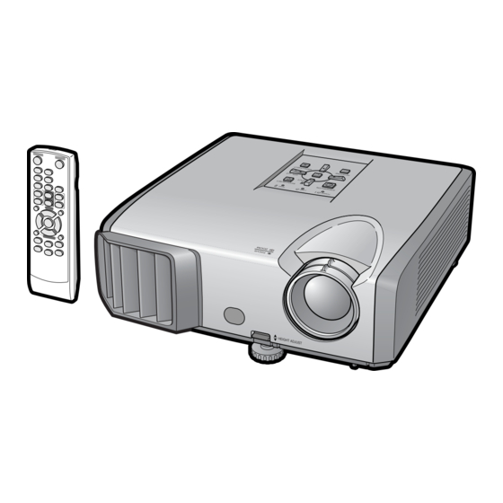
■ Remote receiver AN-C3CP2 ■ 3 RCA to mini D-sub 15 pin cable (3.0 m) • Some of the optional accessories may not be available depending on the region. Please check with your nearest Sharp Authorized Projector Dealer or Service Center. -
Page 112: Part Names And Functions
Part Names and Functions Numbers in refer to the main pages in this operation manual where the topic is explained. Projector Top View Power Lamp indicator 26, 53 26, 53 indicator Temperature warning indicator STANDBY/ON ECO+QUIET button button For lowering the noise For turning the of the cooling fan and power on and... -
Page 113: Rear View
Numbers in refer to the main pages in this operation manual where the topic is explained. Rear View MONITOR OUT terminal Terminals (Output terminal for computer RGB, component and DVI analog AUDIO 1 input terminal signals. Shared for COMPUTER/ COMPONENT and DVI-I) COMPUTER/ Terminal for connecting a COMPONENT input... - Page 114 Part Names and Functions (Continued) STANDBY button ON button For turning the power For putting the projector into the standby mode. FREEZE button COMPUTER, DVI, For freezing images. S-VIDEO, VIDEO buttons AV MUTE button For switching to the For temporarily respective input modes.
-
Page 115: Inserting The Batteries
Inserting the Batteries Pull down the tab on the cover and remove the cover towards the direction of the arrow. Insert the batteries. • Insert the batteries making sure the polarities correctly match the m and n marks inside the battery compartment. Insert the lower tab of the cover into the opening, and lower the cover until it clicks in place. -
Page 116: Quick Start
Quick Start This section shows the basic operation (projector connecting with the computer). For details, see the page described below for each step. Setup and Projection In this section, connection of the projector and the computer is explained using one example. STANDBY/ON STANDBY button button... - Page 117 4. Adjust the projected image with the Setup Guide After the projector turns on, the Setup Guide appears. (When “Setup Guide” is set to “On”. See page 45.) Follow the steps in the Setup Guide and adjust the focus, height (angle) and picture size. After adjusting the focus, height (angle) and picture size, press ENTER to finish the Setup Guide.
-
Page 118: Setting Up The Projector
“Screen Size and Projection Distance”. Ceiling-mount Setup ■ It is recommended that you use the optional Sharp ceiling-mount adaptor and unit for this installation. Before mounting the projector, contact your nearest Sharp Authorized Pro- jector Dealer or Service Center to obtain the recommended ceiling-mount adaptor and unit (sold separately). -
Page 119: Projection (Prj) Mode
Projection (PRJ) Mode The projector can use any of the 4 projection modes shown in the diagram below. Select the mode most appropriate for the projection setting in use. (You can set the PRJ mode in “SCR-ADJ” menu. See page 45.) ■... -
Page 120: Screen Size And Projection Distance
Setting up the Projector (Continued) Screen Size and Projection Distance 4:3 Signal Input (Normal Mode) Picture (Screen) size Projection distance [L] Distance from the lens center to the bottom of the image [H] Diag. [ χ ] Width Height Minimum [L1] Maximum [L2] 300 (762 cm) 610 cm (240 ) -
Page 121: Connecting The Projector To Other Equipment
• Depending on the computer you are using, an image may not be projected unless the computer’s external output port is switched on (e.g. Press “Fn” and “F5” keys simultaneously when using a SHARP notebook computer). Refer to the specific instructions in your computer's operation manual to enable your computer’s external output port. - Page 122 Connecting the Projector to Other Equipment (Continued) Terminal on the Terminal on Equipment Cable connected equipment projector Video equipment HDMI HDMI to DVI cable output (commercially available) terminal DVI-I DVI digital DVI Digital cable (commercially available) output terminal Component 3 RCA to mini D-sub 15 pin cable COMPUTER/ (optional, AN-C3CP2) video...
- Page 123 ø3.5 mm stereo or mono audio cable AUDIO 1 ø3.5 mm (commercially available or available audio output terminal as Sharp service part QCNWGA038WJPZ) RCA audio cable (commercially available) RCA audio output terminal AUDIO 2 Cables for a camera or a video game...
-
Page 124: Controlling The Projector By A Computer
Controlling the Projector by a Computer When the RS-232C terminal on the projector is connected to a computer with a DIN-D-sub RS- 232C adaptor and an RS-232C serial control cable (cross type, commercially available), the com- puter can be used to control the projector and check the status of the projector. Refer to the “SETUP GUIDE”... -
Page 125: Connecting The Power Cord
When connecting to the LAN terminal using a LAN cable TX/RX LED (yellow) Illuminates when transmitting/receiving data. LINK LED (green) Illuminates when linked. * To ensure safety, do not connect the LAN terminal with any cables that may cause excessive voltage such as a telephone line. -
Page 126: Turning The Projector On/Off
Turning the Projector On/Off • When “Auto Restart” is set to “On”: Turning the Projector on If the power cord is unplugged from the outlet or the breaker switch is turned off when the projector is on, then the projector automati- Note that the connections to external equip- cally turns on when the power cord is plugged ment and power outlet should be done be-... -
Page 127: Image Projection
Image Projection Setup Guide screen About the Setup Guide After turning on the projector, the Setup Guide screen appears to assist you with projector setup. Guidance items 1 FOCUS 2 HEIGHT ADJUST 3 ZOOM Press ENTER to exit the Setup Guide screen. - Page 128 Image Projection (Continued) 3 Adjusting the Height The height of the projector can be ad- justed using the adjustment feet at the front and rear of the projector. When the screen is above the projector, the projection image can be made higher by adjusting the projector.
-
Page 129: Correcting Trapezoidal Distortion
Correcting Trapezoidal Distortion Adjustment buttons (P/R/O/Q) When the image is projected either from the top or from the bottom towards the screen at an angle, the image becomes distorted trapezoidally. The function for correcting trapezoidal distortion is called Keystone Correction. RETURN button •... -
Page 130: Switching The Input Mode
Image Projection (Continued) COMPUTER, DVI, Switching the Input Mode S-VIDEO, VIDEO buttons Select the appropriate input mode for the connected equipment. AV MUTE button Press COMPUTER, DVI, S-VIDEO or VIDEO on the remote control to select VOL +/– (Volume) the input mode. buttons •... -
Page 131: Resize Mode
Resize Mode This function allows you to modify or customize the resize mode to enhance the input image. De- pending on the input signal, you can choose a desired image. Press RESIZE. RESIZE • See page for setting on menu screen. button COMPUTER Main resolution... - Page 132 Image Projection (Continued) VIDEO/DTV VIDEO Input signal For 4:3 screen For 16:9 screen Video/DTV Image type NORMAL AREA ZOOM V-STRETCH BORDER STRETCH 4:3 aspect ratio 480I, 480P, 576I, 576P, NTSC, PAL, SECAM Squeeze Letter box 720P, 1035I, 1080I, 1080P 16:9 aspect ratio 16:9 aspect ratio 540P (4:3 aspect ratio in 16:9)
-
Page 133: Operating With The Remote Control
Operating with the Remote Control BREAK TIMER button Displaying the Pointer FREEZE button MAGNIFY buttons Press POINTER and press P/R/ O/Q on the remote control to move POINTER button the pointer. • Press EFFECT to change the pointer icon SPOT button (5 types). -
Page 134: Auto Sync (Auto Sync Adjustment)
Operating with the Remote Control (Continued) Auto Sync Displaying an Enlar ged (Auto Sync Adjustment) Portion of an Image Graphs, tables and other portions of Auto Sync function works when detect- projected images can be enlarged. This ing input signal after the projector turns is helpful when providing more detailed explanations. -
Page 135: Using The Remote Control As The Wireless Computer Mouse
Remote receiver To USB terminal (optional, AN-MR2) To USB terminal USB cable (commercially available or available as Sharp service part QCNWGA014WJPZ) PAGE UP/ The mouse pointer can be oper- PAGE DOWN buttons ated in the following way after it MOUSE/Adjustment is connected. -
Page 136: Menu Items
Page PAGE 1 Movie Game sRGB*1 Picture Net. Help Picture Mode Standard Contrast Contrast Bright Bright Color Color Tint Sharp Tint Sharp Blue Blue Page SEL./ADJ. ENTER PAGE 2 CLR Temp Picture Net. Help Page Picture Mode Standard BrilliantColor™ Page... - Page 137 “Screen adjustment (SCR-ADJ)” menu Main menu Sub menu Pict. SCR-ADJ Net. Help Resize SCR - ADJ Normal Normal Resize Border Area Zoom Full Page Page Image Shift V-Stretch Dot By Dot Border Keystone Area Zoom Image Shift Stretch V-Stretch Page Border OSD Display VIDEO/...
- Page 138 Menu Items (Continued) Main menu “Network” menu Password [Enable/Disable] Network Page Page DHCP Client [On/Off] Page TCP/IP Page MAC Address Page Projector Page “Help” menu The items you can set with the “Help” menu Pict. Net. Help “Help” menu n Page There is no picture or audio •...
-
Page 139: Using The Menu Screen
Using the Menu Screen ENTER button Adjustment buttons (P/R/O/Q) MENU/HELP button ENTER button Adjustment buttons (P/R/O/Q) RETURN button • Press RETURN to return to the previous screen when the menu is displayed. MENU/HELP button Menu Selections (Adjustments) Example: Adjusting “Bright”. •... - Page 140 Using the Menu Screen (Continued) Press P or R and select “Bright” Picture Net. Help to adjust. Picture Mode Picture Mode Standard Standard • The selected item is highlighted. Contrast Bright Blue CLR Temp BrilliantColor C.M.S. Setting C.M.S. Lamp Setting Bright Reset SEL./ADJ.
-
Page 141: Picture Adjustment ("Picture" Menu)
Net. Help Picture Mode Standard Picture Mode Standard Contrast Bright CLR Temp Color BrilliantColor Tint C.M.S. Setting Sharp C.M.S. Progressive 3D Progressive Blue Lamp Setting Bright Reset SEL./ADJ. ENTER SEL./ADJ. ENTER 1 Selecting the Picture Mode The default settings of each item when selecting Picture Mode... -
Page 142: Adjusting The Image
Tint* For making skin For making skin C.M.S.-Value Sets the brightness of the main tones purplish. tones greenish. colors. Sharp* For less For more Reset The adjustments of “Hue”, sharpness. sharpness. “Saturation” and “Value” of all Red* For weaker red. -
Page 143: Progressive
Menu operation n Page 5 Progressive 6 Reducing Image Noise (DNR) Video digital noise reduction (DNR) provides high Selectable Description quality images with minimal dot crawl and cross items color noise. Useful to display fast-moving images such as sports. Progressive Selectable Description items... -
Page 144: Adjusting The Projected Image ("Scr - Adj" Menu)
Adjusting the Projected Image (“SCR - ADJ” Menu) Menu operation n Page Pict. SCR-ADJ Net. Help Resize Border Image Shift Keystone OSD Display Background Logo Setup Guide PRJ Mode Front Language English SEL./ADJ. ENTER 3 Keystone Correction 1 Setting the Resize Mode When the image is projected either from the top or from the bottom towards the screen at an angle, Note... -
Page 145: Selecting The Background Image
Menu operation n Page 5 Selecting the Background 8 Selecting the On-screen Image Display Language Selectable items Description The projector can switch the on-screen display Logo Sharp logo screen language among 17 languages. Blue Blue screen None — English Deutsch Español... -
Page 146: Adjusting The Projector Function ("Prj - Adj" Menu)
Adjusting the Projector Function (“PRJ - ADJ” Menu) Menu operation n Page Pict. PRJ-ADJ Net. Help 3 Auto Restart Function Auto Sync Auto Power Off Selectable Auto Restart Description items STANDBY Mode Standard System Sound If the power cord is unplugged from the Speaker outlet or the breaker switch is turned off Audio Input... -
Page 147: Audio Input
• If you lose or forget your keycode, contact your nearest Sharp Authorized Projector Dealer or Service Center (see page 62). Even if the product warranty is valid, the keycode reset will incur a charge. -
Page 148: Checking The Lamp Life Status
Adjusting the Projector Function (“PRJ - ADJ” Menu) (Continued) Keylock Function Enter the same keycode in “Re- confirm”. Locking the Operation Buttons on the Projector Note Use this function to lock the operation buttons To cancel the keycode that you have already on the projector. -
Page 149: Setting Up The Projector Network Environment ("Network" Menu)
Setting up the Projector Network Environment (“Network” menu) Menu operation n Page Pict. Network Help Password Disable DHCP Client TCP/IP MAC Address X X : X X : X X : X X : X X : X X Projector X X - X X X X SEL./ADJ. -
Page 150: Dhcp Client Setting
Setting up the Projector Network Environment (“Network” menu) (Continued) Menu operation n Page Selectable items Description 2 DHCP Client Setting IP Address Factory default setting: 192. 168.150.002 Connect the LAN cable before turning the pro- Enter an IP address appropri- jector on. -
Page 151: Troubleshooting With The "Help" Menu
Troubleshooting with the “Help” Menu This function advises you to solve the problems during usage. Utilizing the “Help” Menu Functions ENTER button Adjustment buttons Example: When image flickering appears (P/R/O/Q) Operation to solve image flickering when pro- jecting the computer RGB signal. MENU/HELP button Press MENU/HELP. -
Page 152: Maintenance
Maintenance Cleaning the projector Cleaning the lens ■ Ensure that you have unplugged the power ■ Use a commercially available blower or lens cord before cleaning the projector. cleaning paper (for glasses and camera lenses) ■ The cabinet as well as the operation panel is for cleaning the lens. -
Page 153: Maintenance Indicators
Maintenance Indicators ■ The warning lights (power indicator, lamp indicator and temperature warning indicator) on the projector indicate problems inside the projector. ■ If a problem occurs, either the temperature warning indicator or the lamp indicator will illuminate red, and the projector will enter standby mode. After the projector has entered standby mode, follow the procedures given below. - Page 154 (See page 8.) indicator high. • Cooling fan • Take the projector to your breakdown nearest Sharp Authorized • Internal circuit Projector Dealer or Service failure Center (see page 62) for • Clogged air intake repair. Lamp...
-
Page 155: Regarding The Lamp
Sharp Authorized Projector Dealer or Service Center. * If the new lamp does not light after replacement, take your projector to the nearest Sharp Authorized Projector Dealer or Service Center for repair. -
Page 156: Removing And Installing The Lamp Unit
Regarding the Lamp (Continued) Removing and Installing the Lamp Unit Warning! Lamp unit Optional • Do not remove the lamp unit from the projec- accessory AN-F212LP tor right after use. The lamp and parts around the lamp will be very hot and may cause burns or injury. -
Page 157: Resetting The Lamp Timer
Remove the lamp unit. • Loosen the securing screws from the lamp unit. Hold the lamp unit and pull it in the direction of the arrow. At this time, keep the lamp unit horizontal and do not tilt it. Insert the new lamp unit. •... -
Page 158: Storing The Projector
Storing the Projector How to Use the Storage Case When storing the projector, attach the lens cap to the lens, and place it in the supplied storage case. Open the cover of the storage case. Place the projector into the stor- age case. -
Page 159: Computer Compatibility Chart
Computer Compatibility Chart Computer • Multiple signal support Pixel Clock: 12-170 MHz Horizontal Frequency: 15-110 kHz, Sync signal: Compatible with TTL level Vertical Frequency: 45-85 Hz, • Compatible with sync on green signal The following is a list of modes that conform to VESA. However, this projector supports other signals that are not VESA standards. -
Page 160: Troubleshooting
Troubleshooting Problem Check Page • Projector power cord is not plugged into the wall outlet. • Power to the external connected devices is off. – • The selected input mode is wrong. 21–25 • Cables are incorrectly connected to the projector. •... - Page 161 Problem Check Page An unusual sound is • If the picture is normal, the sound is due to cabinet shrinkage caused – occasionally heard from by room temperature changes. This will not affect operation or the cabinet. performance. Maintenance indicator on •...
-
Page 162: For Sharp Assistance
For SHARP Assistance If you encounter any problems during setup or operation of this projector, first refer to the “Troubleshooting” section on pages and 61. If this operation manual does not answer your question, please contact the SHARP Service departments listed below. -
Page 163: Specifications
80% of the above values. Brightness is 2400Lm. As a part of policy of continuous improvement, SHARP reserves the right to make design and specification changes for product improvement without prior notice. The performance specifica- tion figures indicated are nominal values of production units. -
Page 164: Dimensions
Dimensions Units: mm... -
Page 165: Index
ENTER button ............39 Screen Size and Projection Distance ..... 20 Exhaust vent ............12, 52 Setup Guide ............27, 45 Fan Mode ..............47 Sharp ............... 42 Focus ring ..............27 Speaker ..............46 FREEZE button ............34 SPOT button ............33 Front adjustment foot .......... - Page 166 Multimedia PROJECTOR MODEL XG-K230XA SETUP GUIDE Connecting Pin Assignments ......2 Quit without Saving Settings ([Q]Quit Unchanged) .. 24 RS-232C Specifications and Commands ..4 IP Address Setting ([1]IP Address) ...... 25 Setting up the Projector Network Environment ... 9 Subnet Mask Setting ([2]Subnet Mask) ....
-
Page 167: Connecting Pin Assignments
Connecting Pin Assignments COMPUTER/COMPONENT input and COMPUTER/COMPONENT output Terminals : mini D- sub 15 pin female connector COMPUTER Input/Output COMPONENT Input/Output Pin No. Signal Pin No. Signal Video input (red) PR (CR) Video input (green/sync on green) Video input (blue) PB (CB) Not connected Not connected... - Page 168 Connecting Pin Assignments RS-232C Terminal : mini DIN 9 pin female connector Pin No. Signal Name Reference Not connected Receive Data Input Connected to internal circuit Send Data Output Connected to internal circuit Not connected Signal Ground Connected to internal circuit Not connected Request to Send Connected to CS in internal circuit...
-
Page 169: Rs-232C Specifications And Commands
RS-232C Specifications and Commands Computer control A computer can be used to control the projector by connecting an RS-232C serial control cable (cross type, commercially available) to the projector. (See page 24 of the projector’s operation manual for connection.) Communication conditions Set the serial port settings of the computer to match that of the table. - Page 170 Usage Time(Minute) 0, 15, 30, 45 Life(Percentage) 0% – 100%(Integer) XGK230XA Name Model Name Check XG-K230XA Model Name Check Projector Name Setting 1 OK or ERR (First 4 characters) *1 Projector Name Setting 2 OK or ERR (Middle 4 characters) *1...
- Page 171 -30 – +30 OK or ERR Color -30 – +30 OK or ERR Tint -30 – +30 OK or ERR Sharp -30 – +30 OK or ERR CLR Temp -1 – +1 OK or ERR BrilliantColor 0 – +2 OK or ERR...
- Page 172 -30 – +30 OK or ERR Color -30 – +30 OK or ERR Tint -30 – +30 OK or ERR Sharp -30 – +30 OK or ERR CLR Temp -1 – +1 OK or ERR BrilliantColor 0 – +2 OK or ERR...
- Page 173 RS-232C Specifications and Commands RETURN CONTROL CONTENTS COMMAND PARAMETER Standby mode Power ON (or 30-second startup time) Image Shift -96 – +96 OK or ERR OSD Display OK or ERR OK or ERR Video System Auto OK or ERR OK or ERR OK or ERR SECAM NTSC4.43...
-
Page 174: Setting Up The Projector Network Environment
Setting up the Projector Network Environment This section describes the basic procedure for using the projector via the network. If the network is already constructed, the projector’s network settings may need to be changed. Please consult your network administrator for assistance with these settings. You can make network settings both on the projector and on the computer. - Page 175 Setting up the Projector Network Environment 1. Connecting the Pro- jector to a Computer Establishing a one-to-one connection from the projector to a computer. Using a commercially available LAN cable (UTP cable, Category 5, cross-over type) you can configure the pro- jector via the computer.
- Page 176 Setting up the Projector Network Environment 2. Setting an IP Address for the Computer The following describes how to make settings in Windows Vista ® Log on the network using the administrator’s account for the computer. Click “start”, and click “Control Panel”.
- Page 177 Setting up the Projector Network Environment Click “Internet Protocol Version 4 (TCP/IPv4)”, and click the “Properties” button. Confirm or change an IP address for the setup computer. 1 Confirm and note the current IP ad- dress, Subnet mask and Default gateway.
- Page 178 Setting up the Projector Network Environment 3. Setting up a Network Connection for the Projector Settings for such items as the projector’s IP address and subnet mask are compatible with the existing network. Set each item on the projector as follows. (See page 50 of the projector’s operation manual for setting.) DHCP Client : Off...
- Page 179 Setting up the Projector Network Environment The TCP/IP setting screen appears, ready for network set- tings for the projector. Items Setting example / Remarks You can set the password to Password protect the TCP/IP setting. DHCP Select “ON” or “OFF” to determine Client whether to use DHCP Client.
-
Page 180: Controlling The Projector Via Lan
Controlling the Projector via LAN After connecting the projector to your network, enter the projector IP address in “Address” on Internet Explorer (version 5.0 or later) using a computer on the network to start a setup screen that will enable control of the projector via the network. Controlling the Projector Using Internet Explorer (Version 5.0 or later) - Page 181 Controlling the Projector via LAN Confirming the Projector Controlling the Projector Status (Status) (Control) On this screen, you can perform projector control. You can control the following items : • Power On this screen, you can confirm the projector • Input Select status.
- Page 182 Controlling the Projector via LAN Setting and Adjusting the Setting the Security Projector (Settings & Adjustments) (Network – Security) Example: “Picture” screen display for COMPUTER On these screens, you can make projector settings or adjustments. You can set or adjust the following items : •...
- Page 183 Server address for e-mail transmission. Projector Setting the projector name. e.g.1 : 192.168.150.253 Name e.g.2 : smtp123.sharp.co.jp Auto Setting the time interval in * When using a domain name, Logout which the projector will be make settings for the DNS...
- Page 184 Controlling the Projector via LAN Setting Error Items and Setting Error Items and Destination Addresses to the URL that are to be which E-mail is to be Sent Displayed when an Error when an Error Occurs Occurs (Service & Support – (Mail –...
-
Page 185: Setting Up The Projector Using Rs-232C Or Telnet
Setting up the Projector Using RS-232C or Telnet Connect the projector to a computer using RS-232C or Telnet, and open the SETUP MENU on the computer to carry out various settings for the projector. Input “setup” and press the “Enter” When Connecting Using key. - Page 186 Setting up the Projector Using RS-232C or Telnet ▼SETUP MENU When Connecting Using Telnet Click “Start” from the Windows ® desk- top and select “Run”. • If the IP address has been changed, be sure to Enter “telnet 192.168.150.2” in the text box that opens up.
- Page 187 Setting up the Projector Using RS-232C or Telnet ADVANCED SETUP MENU SETUP MENU (Main Menu) ▼SETUP MENU ▼ADVANCED SETUP MENU [1]IP Address IP address settings. (Page 25) [2]Subnet Mask [1]Auto Logout Time (Factory default setting : 5 min- Subnet mask settings. (Page 25) utes) [3]Default Gateway Setting of time until automatic disconnection of net-...
- Page 188 Setting up the Projector Using RS-232C or Telnet Enter number or symbol of item to be selected on the SETUP MENU. When setting, input the details to be set. Setting is carried out one item at a time, and saved at the end. View Setting Detail List Set Items ([V]...
- Page 189 Setting up the Projector Using RS-232C or Telnet Save Settings and Quit Quit without Saving Set- ([S] tings Save & Quit) ([Q]Quit Unchanged) Save set values and quit menu. Quit menu without saving setting values. ▼SETUP MENU ▼SETUP MENU 1 1 1 1 1 Enter “s” and press the “Enter” key. 1 1 1 1 1 Enter “q”...
- Page 190 Setting up the Projector Using RS-232C or Telnet The setting procedure for each item will be explained. For the basic procedure, please refer to “Set Items” on page 23. IP Address Setting Default Gateway Setting ([1]IP Address) ([3]Default Gateway) Setting of IP address. Setting default gateway.
- Page 191 Setting up the Projector Using RS-232C or Telnet Password Setting Projector Name Setting ([7] ([5]Password) Projector Name) Carrying out security protection using password. It is possible to assign a projector name. 1 1 1 1 1 Enter “5” and press the “Enter” key. 1 1 1 1 1 Enter “7”...
- Page 192 Setting up the Projector Using RS-232C or Telnet Disconnecting All Connec- Setting Auto Logout Time tions ([D]Disconnect All) (ADVANCED[1]Auto Logout Time) It is possible to disconnect all the TCP/IP connec- If there is no input after a fixed time, the projector tions currently recognized by the projector.
- Page 193 Setting up the Projector Using RS-232C or Telnet Carrying out Network Ping Setting of Accept IP Ad- Test dress (ADVANCED[6]Accept IP (ADVANCED[5]Network Ping Test) Addr(1) - [8]Accept IP Addr(3)) It is possible to confirm that a network connection It is possible to improve security of the projector by between the projector and a computer etc.
- Page 194 Setting up the Projector Using RS-232C or Telnet Setting of Search Port Return to Main Menu (ADVANCED[0]Search Port) (ADVANCED[Q]Return to Main Menu) Sets the port number used when searching for the Returns to the main SETUP MENU. projector from the network. 1 1 1 1 1 Enter “0”...
-
Page 195: Resetting The Lamp Timer Of The Projector Via Lan
Resetting the Lamp Timer of the Projector via LAN When the projector is connected to a network, you can use the communications program to send a command to reset the lamp timer. The example below uses Windows ® XP as the oper- ®... - Page 196 Resetting the Lamp Timer of the Projector via LAN Click “Properties” on the “File” menu. Click the “Settings” tab, and then click “ASCII Setup”. Select the check boxes next to “Send line ends with line feeds”, “Echo typed characters locally”, and “Append line feeds to in- coming line ends”, and click “OK”.
-
Page 197: Troubleshooting
Troubleshooting Communication cannot be established with the projector When connecting the projector using serial-connection \ Check that the RS-232C terminal of the projector and a computer or the commercially available controller are connected correctly. \ Check that the RS-232C cable is a cross-over cable. \ Check that the RS-232C port setting for the projector corresponds to the setting for the computer or the commercially available controller. - Page 198 Troubleshooting \ Take the following steps for checking the network settings for the computer. 1. Open a command prompt. • In the case of Windows 2000: click “start” ➔ “Programs” ➔ “Accessories” ➔ “Command ® Prompt” in order. • In the case of Windows : click “start”...
- Page 199 Troubleshooting \ Check if the “TCP/IP” protocol is operating correctly using the “PING” command. Also, check if an IP address is set. 1. Open a command prompt. • In the case of Windows 2000: click “start” ➔ “Programs” ➔ “Accessories” ➔ “Command ®...
- Page 200 TINS-D850WJZZ...
Need help?
Do you have a question about the XG-K230XA and is the answer not in the manual?
Questions and answers