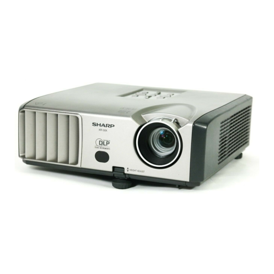
Sharp XR-30S Service Manual
Hide thumbs
Also See for XR-30S:
- Operation manual (71 pages) ,
- Specifications (2 pages) ,
- Specifications (2 pages)
Table of Contents
Advertisement
TopPage
In the interests of user-safety (Required by safety regulations in some countries) the set should be re-
stored to its original condition and only parts identical to those specified should be used.
IMPORTANT SERVICE SAFETY NOTES.............i
Precautions for using lead-free solder ... . ..........vi
[1]
Specifications ......................................... . ....... 1-1
[2]
Parts Name and Basic Operation........... . ....... 1-2
[3]
DIMENSIONS ........................................ . ..... 1-11
[4]
Regarding the lamp................................ . ..... 1-12
[1]
Removing the top Body.......................... . ....... 2-1
[2]
Removing the MAIN PWB...................... . ....... 2-3
[3]
Removing the Speaker Unit ................... . ....... 2-4
[4]
Fan Unit.................................................. . ....... 2-5
[5]
R/C PWB................................................ . ....... 2-6
[6]
Removing the BALLAST POWER PWB........ 2-6
[1]
THE OPTICAL UNIT OUTLINE.............. . ....... 3-1
[1]
ELECTRICAL ADJUSTMENT................ . ....... 4-1
[2]
Adjustment mode process menu............ . ....... 4-4
Parts marked with "
" are important for maintaining the safety of the set. Be sure to replace these parts with specified ones for maintaining the
safety and performance of the set.
SERVICE MANUAL
MULTIMEDIA PROJECTOR
MODELS
CONTENTS
[1]
TROUBLESHOOTING TABLE ......................5-1
[1]
BLOCK DIAGRAM.........................................6-1
[2]
OVERALL WIRING DIAGRAM ......................6-3
CHAPTER 7. PRINTED WIRING BOARD
[1]
MAIN Unit ......................................................7-1
[2]
DMD Unit .......................................................7-9
[3]
BALLAST POWER Unit............................... 7-11
[4]
BALLAST CONTROL Unit...........................7-17
[5]
PHOTO SENSOR Unit ................................7-19
[6]
R/C RECEIVER Unit....................................7-20
[1]
WAVEFORMS ...............................................8-1
[1]
GRAM............................................................9-1
[2]
SCHEMATIC DIAGRAM ................................9-2
XR-30S/XR-30X/XG-F210X
No. S47E3XR-30XS/
XR-30S
XR-30X
XG-F210X
This document has been published to be used for
after sales service only.
The contents are subject to change without notice.
Advertisement
Table of Contents

Related Manuals for Sharp XR-30S


Summary of Contents for Sharp XR-30S
-
Page 1: Table Of Contents
TopPage XR-30S/XR-30X/XG-F210X SERVICE MANUAL No. S47E3XR-30XS/ MULTIMEDIA PROJECTOR XR-30S XR-30X XG-F210X MODELS In the interests of user-safety (Required by safety regulations in some countries) the set should be re- stored to its original condition and only parts identical to those specified should be used. -
Page 2: Safety Precaution
XR-30S/XR-30X/XG-F210X XR-30S SAFETY PRECAUTION Service Manual IMPORTANT SERVICE SAFETY NOTES IMPORTANT SERVICE SAFETY NOTES (for USA) Service work should be performed only by qualified service technicians who are thoroughly familiar with all safety checks and servicing guidelines as follows: WARNING Use an AC voltmeter with sensitivity of 5000 ohm per volt., or higher, sensitivity to measure the AC voltage... - Page 3 XR-30S/XR-30X/XG-F210X PRECAUTIONS A PRENDRE LORS DE LA REPARATION Ne peut effectuer la réparation qu' un technicien spécialisé qui s'est parfaitement accoutumé à toute vérification de sécurité et aux conseils suivants. AVERTISSEMENT Utiliser un voltmètre CA d'une sensibilité d'au moins 1. N'entreprendre aucune modification de tout circuit.
-
Page 4: Note To Service Personnel
XR-30S/XR-30X/XG-F210X NOTE TO SERVICE NOTE POUR LE PERSONNEL PERSONNEL D’ENTRETIEN ////////////////////////////////////////////////////////////// ////////////////////////////////////////////////////////////// UV-RADIATION PRECAUTION PRECAUTION POUR LES RADIATIONS UV ////////////////////////////////////////////////////////////// ////////////////////////////////////////////////////////////// La source de lumière, la lampe, dans le projecteur émet The light source, lamp, in the projector emits small de petites quantités de radiation UV. -
Page 5: Lamp Replacement
XR-30S/XR-30X/XG-F210X //////////////////////////////////////////////////////////////// //////////////////////////////////////////////////////////////// UV-RADIATION PRECAUTION (Continued) PRECAUTION POUR LES RADIA TIONS UV (Suite) //////////////////////////////////////////////////////////////// //////////////////////////////////////////////////////////////// Lamp Replacement Remplacement de la lampe Note: Remarque: Since the lamp reaches a very high temperature during Comme la lampe devient très chaude pendant le units operation replacement of the lamp should be fonctionnement de l’unité, son remplacement ne doit... -
Page 6: Power Unit
XR-30S/XR-30X/XG-F210X WARNING: High brightness light source, do not stare into the beam of light, or view directly. Be especially careful that children do not stare directly into the beam of light. WARNING: TO REDUCE THE RISK OF FIRE OR ELECTRIC SHOCK, DO NOT EXPOSE THIS UNIT TO MOISTURE OR WET LOCATIONS. -
Page 7: Precautions For Using Lead-Free Solder
XR-30S/XR-30X/XG-F210X Precautions for using lead-free solder Employing lead-free solder • "PWBs" of this model employs lead-free solder. The LF symbol indicates lead-free solder, and is attached on the PWBs and service manuals. The alphabetical character following LF shows the type of lead-free solder. -
Page 8: Chapter 1. Operation Manual Specifications
Weight 6.4 lbs. (2.9 kg) As a part of policy of continuous improvement, SHARP reserves the right to make design and specification changes for product improvement without prior notice. The performance specifica- tion figures indicated are nominal values of production units. There may be some deviations from these values in individual units. -
Page 9: Parts Name And Basic Operation
XR-30S/XR-30X/XG-F210X [2] Parts Name and Basic Operation Top View Power Lamp indicator indicator Temperature warning indicator STANDBY/ON ECO+QUIET button button For lowering the noise For turning the of the cooling fan and power on and extending the lamp life. putting the... - Page 10 XR-30S/XR-30X/XG-F210X Rear View (For XR-30S, XR-30X) Terminals AUDIO 1 input terminal S-VIDEO input terminal Terminal for connecting video equipment with an DVI-D input terminal S-video terminal. Terminal for DVI digital RGB and RS-232C terminal digital component Terminal for signals. controlling the...
- Page 11 XR-30S/XR-30X/XG-F210X Rear View (For XG-F210X) Terminals AUDIO 1 input terminal S-VIDEO input terminal Terminal for connecting video equipment with an DVI-I input terminal S-video terminal. Terminal for DVI digital, computer RS-232C terminal RGB, and Terminal for component signals. controlling the...
- Page 12 XR-30S/XR-30X/XG-F210X STANDBY button ON button For putting the For turning the projector into the power on. standby mode. FREEZE button COMPUTER, DVI, For freezing images. S-VIDEO, VIDEO buttons AV MUTE button For switching to the For temporarily respective input displaying a black modes.
-
Page 13: Inserting The Batteries
XR-30S/XR-30X/XG-F210X Inserting the Batteries Pull down the tab on the cover and remove the cover towards the direction of the arrow. Insert the batteries. Insert the batteries making sure the polarities correctly match marks inside the battery compartment. Insert the lower tab of the cover into the opening, and lower the cover until it clicks in place. - Page 14 XR-30S/XR-30X/XG-F210X Connecting Pin Assignments (For XR-30S/XR-30X) COMPUTER/COMPONENT input and COMPUTER/COMPONENT output Terminals:mini D-sub 15 pin female connector COMPUTER Input/Output COMPONENT Input/Output Pin No. Signal Pin No. Signal Video input (red) PR (CR) Video input (green/sync on green) Video input (blue)
- Page 15 XR-30S/XR-30X/XG-F210X RS-232C Terminal: D-sub 9 pin male connector of the DIN-D-sub RS-232C adaptor Pin No. Signal Name Reference Not connected Receive Data Input Connected to internal circuit Send Data Output Connected to internal circuit Not connected Signal Ground Connected to internal circuit...
- Page 16 XR-30S/XR-30X/XG-F210X Connecting Pin Assignments (For XG-F210X) COMPUTER/COMPONENT input and COMPUTER/COMPONENT output Terminals: mini D-sub 15 pin female connector COMPUTER Input/Output COMPONENT Input/Output Pin No. Signal Pin No. Signal Video input (red) PR (CR) Video input (green/sync on green) Video input (blue)
- Page 17 XR-30S/XR-30X/XG-F210X RS-232C Terminal: mini DIN 9 pin female connector Pin No. Signal Name Reference Not connected Receive Data Input Connected to internal circuit Send Data Output Connected to internal circuit Not connected Signal Ground Connected to internal circuit Not connected...
-
Page 18: Dimensions
XR-30S/XR-30X/XG-F210X [3] DIMENSIONS Units: inches (mm) (75) (60) (270) (10) (10) (36) (75) 1 – 11... -
Page 19: Regarding The Lamp
Sharp Authorized Projector Dealer or Service Center. * If the new lamp does not light after replacement, take your projector to the nearest Sharp Authorized Projector Dealer or Service Center for repair. -
Page 20: Removing And Installing The Lamp Unit
XR-30S/XR-30X/XG-F210X Removing and Installing the Lamp Unit Warning! Lamp unit Optional Do not remove the lamp unit from the projec- AN-XR30LP accessory tor right after use. The lamp and parts around the lamp will be very hot and may cause burns or injury. -
Page 21: Resetting The Lamp Timer
XR-30S/XR-30X/XG-F210X Remove the lamp unit. Loosen the securing screws from the lamp unit. Hold the lamp unit and pull it in the direction of the arrow. At this time, keep the lamp unit horizontal and do not tilt it. Insert the new lamp unit. -
Page 22: Chapter 2. Removing Of Major Parts
XR-30S/XR-30X/XG-F210X CHAPTER 2. XR-30S REMOVING OF MAJOR PARTS Service Manual [1] Removing the top Body 1. Detach the Lens Cap. 2. Please rotate the Focus Ring. Lens Cap It turns to the direction of the arrow to all the way. - Page 23 XR-30S/XR-30X/XG-F210X 3. Remove the 1 lock screw , 7 lock screws and detach the Top Body. Bottom Body Bottom Body Top Body Top Body 2 – 2...
-
Page 24: Removing The Main Pwb
XR-30S/XR-30X/XG-F210X [2] Removing the MAIN PWB 1. Remove the 3 lock screws , 2 lock screws , 1 lock screw and 3 lock screws and detach the Main PWB. Bottom Body MAIN PWB MAIN PWB Remove the main PWB opening up the rear terminal section. -
Page 25: Removing The Speaker Unit
XR-30S/XR-30X/XG-F210X [3] Removing the Speaker Unit 1. Remove the speaker. Speaker Speaker 2 – 4... -
Page 26: Removing The Optical Mechanism Unit And Fan Unit
XR-30S/XR-30X/XG-F210X [4] Removing the Optical Mechanism Unit and Fan Unit 1. Remove the Fan unit. 2. Remove the 2 lock screws , and detach the socket. Fan Unit 3. Remove the 4 lock screws and 1 lock screw and detach the Optical Mechanism Unit. -
Page 27: Removing The Ballast Power Unit And R/C Pwb
XR-30S/XR-30X/XG-F210X [5] Removing the BALLAST POWER Unit and R/C PWB 1. The lead wire of LFSW is removed from the cut mouth of the insulated seat. 2. Remove the 4 lock screws and detach the BALLAST POWER Unit. 3. Remove the R/C PWB. - Page 28 XR-30S/XR-30X/XG-F210X 2. Detach the Insulation seat. 3. Remove the 3 lock screws and detach the Power Shield (Top). Insulation seat Insulation seat Power Shield (Top) Ballast Power Unit 2 – 7...
- Page 29 XR-30S/XR-30X/XG-F210X 4. Remove the Rivet 5. Remove the 1 lock screws and detach the Ballast Power PWB. Ballast Power PWB Remove the PWB in the slanting position Power Shield (Bottom) opening up the insulating plate. 2 – 8...
-
Page 30: Chapter 3. The Optical Unit Outline
XR-30S/XR-30X/XG-F210X CHAPTER 3. XR-30S THE OPTICAL UNIT OUTLINE Service Manual [1] THE OPTICAL UNIT OUTLINE 1. Layout for proper setup of the optical components and parts (top view) (Schematic diagram) Projection Lens UV Glass Lamp Color Wheel Item Function Lamp Light source. - Page 31 XR-30S/XR-30X/XG-F210X 2. When the DMD unit has been replaced. If shading shown in Figure 1 appears on the screen after replacing DMD, turn the adjustment screw of the optical engine to adjust the lighting area of DMD. Fig. 1 Shading 1) Loosen the adjustment lever fixing screw .
- Page 32 XR-30S/XR-30X/XG-F210X "Fixing and checking method of the focus ring base" 1) Match the paint mark and the mark as shown in the figure. Adjust the mark. Adjust the paint mark. About 1.6mm 2) Fully turn the focus ring base in the anticlockwise direction viewed from the front. At this time, adjust the zoom to any position.
-
Page 33: Chapter 4. Electrical Adjustment Electrical Adjustment
XR-30S/XR-30X/XG-F210X CHAPTER 4. XR-30S ELECTRICAL ADJUSTMENT Service Manual [1] ELECTRICAL ADJUSTMENT Adjusting point Adjusting conditions Adjusting procedure •Make the following settings. EEPROM 1. Turn on the power (with the lamp on) and initialization warm up the set for 15 minutes. - Page 34 DVI input operation check Send the video signal to the DVI terminal. 1. For XR-30S/X, check that an image is properly pro- jected through the digital input. 2. For XG-F210X, check that an image is properly projected through the digital input and analog input.
- Page 35 XR-30S/XR-30X/XG-F210X Adjusting point Adjusting conditions Adjusting procedure RS232C operation check 1. Connect the unit and a PC with the 1. Send a command from the PC, and check it func- RS232C cable. tions correctly. Model name and version check 1. Select the following group.
-
Page 36: Adjustment Mode Process Menu
XR-30S/XR-30X/XG-F210X [2] Adjustment mode process menu 1st Layer 2nd Layer Default 1st Layer 2nd Layer Default ADJUST CW/Auto KS CW-INDEX OTHER SPECIAL USB-MODE HDCP-MODE K-SENS PULSE-MODE AD/DLP R-CONT EDID EEP-SELECT G-CONT EEP-WP B-CONT EXIT R-GAIN G-GAIN B-GAIN — — —... - Page 37 XR-30S/XR-30X/XG-F210X 1. Adjustment of ballast unit output power (lamp power) 1. List of parts requiring adjustment When replacing the following parts, adjust the ballast unit output power (lamp power). Part name Ref No. Part code Cement resistor R923 RR-FZA002WJZZ Ballast Control PWB ——...
-
Page 38: Chapter 5. Troubleshooting Table
XR-30S/XR-30X/XG-F210X CHAPTER 5. XR-30S TROUBLESHOOTING TABLE Service Manual [1] TROUBLESHOOTING TABLE Checking the basic operation Has P1701 come off or is it Does the power LED light Fully insert the connector. loose? up or flash in red or green? Does the set function with its keys or the remote Go to "Main PWB check". - Page 39 XR-30S/XR-30X/XG-F210X IC2263, IC2232 and peripheral circuits. 5 – 2...
- Page 40 XR-30S/XR-30X/XG-F210X DMD system check Check P2501 for breakage and solder crack and peripheral resistance for solder crack. Check SC9101 for breakage and solder crack. Is there any vertical stripe (block noise) on the Screen? Is the screen all black? The main PWB and DMD PWB are in poor contact.
- Page 41 XR-30S/XR-30X/XG-F210X Power supply PWB check Is 13 V applied to pins (3), (4), (5) and (6) of the connector P704? Does the lamp turn on? Check the main PWB. Are connectors P704 and Securely insert the CN901 fully inserted? connectors.
- Page 42 XR-30S/XR-30X/XG-F210X Are connectorsP701 and Securely insert the connectors. P702 fully inserted? Is AC voltage between 100 Replace F701. 240 V applied to both ends of C702? Press the red button on the Is the bimetal broken? bimetal. (Connection between 1 and...
- Page 43 XR-30S/XR-30X/XG-F210X Checking the lamp light-up Go to "Check when the Does the lamp turn on lamp turns off soon after when the power is turned turning on". Securely insert the Is the lamp tight in the connectors. socket? Has the FPC cable to...
- Page 44 XR-30S/XR-30X/XG-F210X Check when the lamp turns off soon after turning on Have connectors P1703, Securely insert the P1721, P1722 and P1723 come off or are they connectors. loose? Is each cooling fan Check the cooling fan. rotating? Check peripheral circuits of Is approx.
- Page 45 XR-30S/XR-30X/XG-F210X RGB DVI-Analog and component signal check Send component signal or RGB signal of 1080i (or 720P) from COMPUTER/ COMPONENT Terminal or DVI-I Terminal (ANALOG RGB SIGNAL: XG-F210X only) Select COMPUTER or DVI-Analog (only XG-F210X) using keys on the main unit or the remote control.
- Page 46 XR-30S/XR-30X/XG-F210X DVI digital input check Send the DVI digital signal to the DVI-I Terminal (XG-F210X), DVI-D Terminal (XR-30S or XR-30X). Select "DVI-D Computer" using the keys on the main unit or the remote controller. Does an image appear properly? Is the DVI signal supplied to R3231,...
- Page 47 XR-30S/XR-30X/XG-F210X VIDEO check S-VIDEO check Send S-Video signal (color Send VIDEO signal from signal) from S-Video VIDEO Terminal. Use Terminal. Select S-Video buttons on the main unit or using keys on the main unit the remote control to select or the remote control.
-
Page 48: Chapter 6. Block Diagram/Overall Wiring Diagram Block Diagram
XR-30S/XR-30X/XG-F210X CHAPTER 6. XR-30S BLOCK DIAGRAM/OVERALL WIRING DIAGRAM Service Manual [1] BLOCK DIAGRAM BLOCK DIAGRAM BALLAST POWER UNIT LAMP BIMETAL Low Voltage Starter DC-DC Converter D907, T902, R939 Q901 C919, C922 uPD78F9177A IC7701 IC7707 IC704 IC707 SP_MUTE Audio AMP S+,S-... -
Page 49: Intake Fan
XR-30S/XR-30X/XG-F210X MAIN UNIT LAMP STDBY(G/R) LAMP(G/R) TEMP(R) MB88346 IC3561 Temp. Sensor LAMP FAN 16F819 TEMP1 Temp. Sensor INTAKE FAN IC3562 FAN CTRL Q1721 Q1723 Q1724 EXHAUST FAN FANLOCK Leaf SW RC UNIT FAN0/1/2 SENSOR UNIT Photo Sensor IC1102 Comparator CWINDEX... -
Page 50: Overall Wiring Diagram
XR-30S/XR-30X/XG-F210X [2] OVERALL WIRING DIAGRAM OVERALL WIRING DIAGRAM 6 – 3... - Page 51 XR-30S/XR-30X/XG-F210X 6 – 4...
-
Page 52: Main Unit
XR-30S/XR-30X/XG-F210X CHAPTER 7. XR-30S PRINTED WIRING BOARD Service Manual [1] MAIN Unit MAIN Unit (Side-A) 7 – 1... - Page 53 XR-30S/XR-30X/XG-F210X 7 – 2...
- Page 54 XR-30S/XR-30X/XG-F210X MAIN Unit (Chip Parts Side-A) 7 – 3...
- Page 55 XR-30S/XR-30X/XG-F210X 7 – 4...
- Page 56 XR-30S/XR-30X/XG-F210X MAIN Unit (Side-B) 7 – 5...
- Page 57 XR-30S/XR-30X/XG-F210X 7 – 6...
- Page 58 XR-30S/XR-30X/XG-F210X MAIN Unit (Chip Parts Side-B) 7 – 7...
- Page 59 XR-30S/XR-30X/XG-F210X 7 – 8...
-
Page 60: Dmd Unit
XR-30S/XR-30X/XG-F210X [2] DMD Unit DMD Unit (Side-A) DMD Unit (Chip Parts Side-A) 7 – 9... - Page 61 XR-30S/XR-30X/XG-F210X DMD Unit (Side-B) DMD Unit (Chip Parts Side-B) 7 – 10...
-
Page 62: Ballast Power Unit
XR-30S/XR-30X/XG-F210X [3] BALLAST POWER Unit BALLAST POWER Unit (Side-A) 7 – 11... - Page 63 XR-30S/XR-30X/XG-F210X 7 – 12...
- Page 64 XR-30S/XR-30X/XG-F210X BALLAST POWER Unit (Sid-B) 7 – 13...
- Page 65 XR-30S/XR-30X/XG-F210X 7 – 14...
- Page 66 XR-30S/XR-30X/XG-F210X BALLAST POWER Unit (Chip Parts Side-B) R760 R758 R718 R704 R706 R705 R761 C715 D724 C701 R713 R738 R703 D707 D710 R702 R701 R712 R756 R724 D709 R715 D722 C719 C718 R714 R726 C751 D713 C727 D712 C708 R727...
- Page 67 XR-30S/XR-30X/XG-F210X R937 C913 R930 R931 R932 R925 R934 R933 Q905 R926 R940 R928 Q906 D904 R942 C921 C908 C909 R919 R920 R905 R904 R903 R902 R901 C923 C924 R921 R922 Q903 FB902 R916 FB901 R907 R911 C907 R917 R913 R906...
-
Page 68: Ballast Control Unit
XR-30S/XR-30X/XG-F210X [4] BALLAST CONTROL Unit BALLAST CONTROL Unit (Side-A) BALLAST CONTROL Unit (Chip Parts Side-A) 7 – 17... - Page 69 XR-30S/XR-30X/XG-F210X BALLAST CONTROL Unit (Side-B) BALLAST CONTROL Unit (Chip Parts Side-B) 7 – 18...
-
Page 70: Photo Sensor Unit
XR-30S/XR-30X/XG-F210X [5] PHOTO SENSOR Unit PHOTO SENSOR Unit (Side-A) PHOTO SENSOR Unit (Chip Parts Side-A) PHOTO SENSOR Unit (Side-B) PHOTO SENSOR Unit (Chip Parts Side-B) 7 – 19... -
Page 71: R/C Receiver Unit
XR-30S/XR-30X/XG-F210X [6] R/C RECEIVER Unit R/C RECEIVER Unit (Side-A) R/C RECEIVER Unit (Chip Parts Side-A) R/C RECEIVER Unit (Side-B) R/C RECEIVER Unit (Chip Parts Side-B) 7 – 20... -
Page 72: Chapter 8. Waveforms
XR-30S/XR-30X/XG-F210X CHAPTER 8. XR-30S WAVEFORMS Service Manual [1] WAVEFORMS (9/9) (6/9) (9/9) TL3210 TL3214 TL730, 731 (2/9) (2/9) BALLAST POWER 8 – 1... -
Page 73: Chapter 9. Schematic Diagram
XR-30S/XR-30X/XG-F210X CHAPTER 9. XR-30S SCHEMATIC DIAGRAM Service Manual [1] DESCRIPTION OF SCHEMATIC DIA- GRAM 1. VOLTAGE MEASUREMENT CONDITION: 1. Voltages at test points are measured at the supply voltage of AC 100V/CROSS 10V-240. Signals are fed by a color bar signal gener- ator for servicing purpose and the above voltages are measured with a 20k ohm/V tester. -
Page 74: Schematic Diagram
XR-30S/XR-30X/XG-F210X [2] SCHEMATIC DIAGRAM MAIN Unit-1 (XR-30S/XR-30X) 9 – 2... - Page 75 XR-30S/XR-30X/XG-F210X 9 – 3...
- Page 76 XR-30S/XR-30X/XG-F210X MAIN Unit-1 (XG-F210X) 9 – 4...
- Page 77 XR-30S/XR-30X/XG-F210X 9 – 5...
- Page 78 XR-30S/XR-30X/XG-F210X MAIN Unit-2 (XR-30S/XR-30X) 9 – 6...
- Page 79 XR-30S/XR-30X/XG-F210X 9 – 7...
- Page 80 XR-30S/XR-30X/XG-F210X MAIN Unit-2 (XG-F210X) 9 – 8...
- Page 81 XR-30S/XR-30X/XG-F210X 9 – 9...
- Page 82 XR-30S/XR-30X/XG-F210X MAIN Unit-3 9 – 10...
- Page 83 XR-30S/XR-30X/XG-F210X 9 – 11...
- Page 84 XR-30S/XR-30X/XG-F210X MAIN Unit-4 9 – 12...
- Page 85 XR-30S/XR-30X/XG-F210X 9 – 13...
- Page 86 XR-30S/XR-30X/XG-F210X MAIN Unit-5 9 – 14...
- Page 87 XR-30S/XR-30X/XG-F210X 9 – 15...
- Page 88 XR-30S/XR-30X/XG-F210X MAIN Unit-6 9 – 16...
- Page 89 XR-30S/XR-30X/XG-F210X 9 – 17...
- Page 90 XR-30S/XR-30X/XG-F210X MAIN Unit-7 (XR-30S) 9 – 18...
- Page 91 XR-30S/XR-30X/XG-F210X 9 – 19...
- Page 92 XR-30S/XR-30X/XG-F210X MAIN Unit-7 (XR-30X/XG-F210X) 9 – 20...
- Page 93 XR-30S/XR-30X/XG-F210X 9 – 21...
- Page 94 XR-30S/XR-30X/XG-F210X MAIN Unit-8 9 – 22...
- Page 95 XR-30S/XR-30X/XG-F210X 9 – 23...
- Page 96 XR-30S/XR-30X/XG-F210X MAIN Unit-9 9 – 24...
- Page 97 XR-30S/XR-30X/XG-F210X 9 – 25...
- Page 98 XR-30S/XR-30X/XG-F210X DMD Unit-1 9 – 26...
- Page 99 XR-30S/XR-30X/XG-F210X 9 – 27...
- Page 100 XR-30S/XR-30X/XG-F210X DMD Unit-2 9 – 28...
- Page 101 XR-30S/XR-30X/XG-F210X 9 – 29...
- Page 102 XR-30S/XR-30X/XG-F210X DMD Unit-3 9 – 30...
- Page 103 XR-30S/XR-30X/XG-F210X 9 – 31...
- Page 104 XR-30S/XR-30X/XG-F210X BALLAST POWER Unit 9 – 32...
- Page 105 XR-30S/XR-30X/XG-F210X AND SHADED COMPONENTS=SAFETY RELATED PARTS 9 – 33...
- Page 106 XR-30S/XR-30X/XG-F210X BALLAST CONTROL Unit 9 – 34...
- Page 107 XR-30S/XR-30X/XG-F210X AND SHADED COMPONENTS=SAFETY RELATED PARTS 9 – 35...
- Page 108 XR-30S/XR-30X/XG-F210X PHOTO SENSOR Unit 9 – 36...
- Page 109 XR-30S/XR-30X/XG-F210X 9 – 37...
- Page 110 XR-30S/XR-30X/XG-F210X R/C RECEIVER Unit 9 – 38...
- Page 111 XR-30S/XR-30X/XG-F210X 9 – 39...
- Page 112 XR-30S/XR-30X/XG-F210X — MEMO — 9 – 40...
-
Page 113: Parts Guide
XR-30S/XR-30X/XG-F210X PartsGuide PARTS GUIDE No. S47E3XR-30XS/ MULTIMEDIA PROJECTOR XR-30S XR-30X XG-F210X MODELS Note: The reference numbers on the PWB are arranged in alphabetical order. CONTENTS PRINTED WIRING BOARD DUNTKE154WEF0 (DMD Unit) ASSEMBLIES CABINET AND MECHANICAL DUNTKE149WEF0 PARTS (BALLAST POWER Unit) - Page 114 (DUNTKE149WEF0). BALLAST CONTROL Unit DUNTKE150WEF0 PHOTO SENSOR Unit DUNTKE151WEF0 DUNTKE152WEF0 R/C RECEIVER Unit MAIN Unit (XR-30X) DUNTKE153FMF0 MAIN Unit (XR-30S) DUNTKE153FMF1 MAIN Unit (XG-F210X) DUNTKE153FMF4 DMD Unit (without the DMD chip) DUNTKE154WEF0 [2] DUNTKE149WEF0 (BALLAST POWER Unit) C701 RC-KZA111WJZZY...
- Page 115 XR-30S/XR-30X/XG-F210X PRICE PART PARTS CODE DESCRIPTION RANK MARK DELIVERY [2] DUNTKE149WEF0 (BALLAST POWER Unit) D722 Zener Diode PTZTE2516B RH-EX1015GEZZY D723 Zener Diode PTZTE2533B RH-EXA359WJZZY D724 Diode D1FL20U VHDD1FL20U/-1Y D901 Zener Diode UDZSTE-1720B RH-EXA097WJZZY D902 Diode RB160M-40TR VHDRB160M40-1Y D903 RH-DXA074WJZZ Diode SF10L60U-7100...
- Page 116 XR-30S/XR-30X/XG-F210X PRICE PART PARTS CODE DESCRIPTION RANK MARK DELIVERY [2] DUNTKE149WEF0 (BALLAST POWER Unit) R739 Resistor 13k 1/16W Metal Film VRN-CY1JF133DY R740 Resistor 4.7 1/2W Metal Film VRN-SV2HC4R7JY R741 Resistor 390k 1/16W Metal Film VRN-TV1JD394DY R742 Resistor 10 1/4W Metal Oxide...
- Page 117 XR-30S/XR-30X/XG-F210X PRICE PART PARTS CODE DESCRIPTION RANK MARK DELIVERY [3] DUNTKE150WEF0 (BALLAST CONTROL Unit) C7701 Capacitor 470p 50V Ceramic VCCCCY1HH471JY C7702 Capacitor 0.22 16V Ceramic VCKYCY1CB224KY C7704 Capacitor 0.1 25V Ceramic VCKYCY1EF104ZY C7705 Capacitor 0.1 25V Ceramic VCKYCY1EF104ZY C7706 Capacitor 0.068 25V Ceramic...
- Page 118 XR-30S/XR-30X/XG-F210X PRICE PART PARTS CODE DESCRIPTION RANK MARK DELIVERY [3] DUNTKE150WEF0 (BALLAST CONTROL Unit) R7711 Resistor 10k 1/16W Metal Oxide VRS-CY1JF103JY R7712 Resistor 100 1/16W Metal Oxide VRS-CY1JF101JY R7713 Resistor 1.8k 1/16W Metal Oxide VRS-CY1JF182JY R7714 Resistor 12k 1/16W Metal Oxide...
- Page 119 XR-30S/XR-30X/XG-F210X PRICE PART PARTS CODE DESCRIPTION RANK MARK DELIVERY [3] DUNTKE150WEF0 (BALLAST CONTROL Unit) R7805 Variable Resistor RVR-M4555CEZZY R7806 Resistor 10k 1/16W Metal Oxide VRS-CY1JF103JY R7807 Resistor 470 1/16W Metal Oxide VRS-CY1JF471JY R7808 Resistor 10k 1/16W Metal Oxide VRS-CY1JF103JY R7810...
- Page 120 XR-30S/XR-30X/XG-F210X PRICE PART PARTS CODE DESCRIPTION RANK MARK DELIVERY [6] DUNTKE153FMF0/1/4 (MAIN Unit) C1771 Capacitor 0.1 25V Ceramic VCKYCY1EF104ZY C1773 Capacitor 1500p 50V Ceramic VCKYCY1HB152KY C1774 Capacitor 0.1 25V Ceramic VCKYCY1EF104ZY C1775 Capacitor 0.1 16V Ceramic VCKYCY1CB104KY C1778 Capacitor 68 10V Electrolytic...
- Page 121 XR-30S/XR-30X/XG-F210X PRICE PART PARTS CODE DESCRIPTION RANK MARK DELIVERY [6] DUNTKE153FMF0/1/4 (MAIN Unit) C2248 Capacitor 4p 50V Ceramic VCCCCY1HH4R0CY C2250 Capacitor 100p 50V Ceramic VCCCCY1HH101JY C2251 Capacitor 0.01 50V Ceramic VCKYCY1HF103ZY C2252 Capacitor 0.01 50V Ceramic VCKYCY1HF103ZY C2253 Capacitor 0.01 50V Ceramic...
- Page 122 XR-30S/XR-30X/XG-F210X PRICE PART PARTS CODE DESCRIPTION RANK MARK DELIVERY [6] DUNTKE153FMF0/1/4 (MAIN Unit) C3308 Capacitor 100p 50V Ceramic VCCCCY1HH101JY C3309 Capacitor 1 50V Electrolytic VCEAPF1HW105MY C3310 Capacitor 1 50V Electrolytic VCEAPF1HW105MY C3311 Capacitor 0.1 25V Ceramic VCKYCY1EF104ZY C3312 Capacitor 150p 50V Ceramic...
- Page 123 XR-30S/XR-30X/XG-F210X PRICE PART PARTS CODE DESCRIPTION RANK MARK DELIVERY [6] DUNTKE153FMF0/1/4 (MAIN Unit) D1722 Diode 1PS184 VHD1PS184++-1Y D1723 Diode RB551V-30TE-17 VHDRB551V30-1Y D1724 Diode RB551V-30TE-17 VHDRB551V30-1Y D1725 Diode RB551V-30TE-17 VHDRB551V30-1Y D1730 Diode RB551V-30TE-17 VHDRB551V30-1Y D1732 VHDRB551V30-1Y Diode RB551V-30TE-17 D1733 Diode RB551V-30TE-17...
- Page 124 IC TC7SH02FU(T5L,JF,T VHiTC7SH02U1EY IC2231 IC PQ018EZ5MZPH VHiPQ018EZ5-1Y IC2232 IC K4S641632K-UC75 RH-iXB742WJZZQ IC2241 IC W134MSQCT(CG6225AAT) VHiW134MSQC-1Y IC2261 IC BR24L32F-WE2 VHiBR24L32F-1Y IC iXC118WJZZ (F-ROM) (XR-30S) If this IC is replaced, execute the model setting in IC2262 RH-iXC118WJZZQ the adjustment item. (See page 4-1.)
- Page 125 IC iXC109WJZZ (F-ROM) (XR-30X/XG-F210X) If this IC is replaced, execute the model IC2262 RH-iXC109WJZZQ setting in the adjustment item. (See page 4-1.) IC2561 IC ISL83220ECVZ-T VHiiSL83220-1Y IC2801 IC iXC116WJZZ (EEPROM) (XR-30S) RH-iXC116WJZZS IC2801 IC iXC112WJZZ (EEPROM) (XR-30X/XG-F210X) RH-iXC112WJZZS IC2802 VHiLV4053AT-1Y IC SN74LV4053APWR...
- Page 126 XR-30S/XR-30X/XG-F210X PRICE PART PARTS CODE DESCRIPTION RANK MARK DELIVERY [6] DUNTKE153FMF0/1/4 (MAIN Unit) Q2573 Transistor 2SA1530A-T112-1R VS2SA1530AR-1Y Q2574 Transistor 2SA1530A-T112-1R VS2SA1530AR-1Y Q2575 Transistor 2SA1530A-T112-1R VS2SA1530AR-1Y Q2801 Transistor PDTC114EE,115 VSRDTC114EE-1Y Q2802 Transistor PDTC114EE,115 VSRDTC114EE-1Y Q2803 VSRDTC114EE-1Y Transistor PDTC114EE,115 Q2804 Transistor UM6K1N TN...
- Page 127 XR-30S/XR-30X/XG-F210X PRICE PART PARTS CODE DESCRIPTION RANK MARK DELIVERY [6] DUNTKE153FMF0/1/4 (MAIN Unit) R1782 Resistor 560 1/2W Metal Oxide VRS-TW2HF561JY R1783 Resistor 560 1/2W Metal Oxide VRS-TW2HF561JY R1784 Resistor 0 1/16W Metal Oxide VRS-CY1JF000JY R1787 Resistor 470k 1/16W Metal Oxide...
- Page 128 [6] DUNTKE153FMF0/1/4 (MAIN Unit) R2261 Resistor 10 1/16W Metal Oxide VRS-CJ1JF100JY R2263 Resistor 10k 1/16W Metal Oxide VRS-CY1JF103JY R2501 Resistor 2.7k 1/16W Metal Oxide (XR-30S) VRS-CH1JF272JY R2502 Resistor 2.7k 1/16W Metal Oxide (XR-30S) VRS-CH1JF272JY R2503 Resistor 39 1/16W Metal Oxide (XR-30X/XG-F210X) VRS-CH1JF390JY...
- Page 129 R2856 Resistor 100 1/16W Metal Oxide (XG-F210X) VRS-CY1JF101JY R2857 Resistor 0 1/16W Metal Oxide (XG-F210X) VRS-CY1JF000JY R2859 Resistor 0 1/16W Metal Oxide (XR-30S/30X) VRS-CY1JF000JY R2860 VRS-CY1JF000JY Resistor 0 1/16W Metal Oxide (XR-30S/30X) R2861 VRS-CY1JF000JY Resistor 0 1/16W Metal Oxide (XR-30S/30X)
- Page 130 XR-30S/XR-30X/XG-F210X PRICE PART PARTS CODE DESCRIPTION RANK MARK DELIVERY [6] DUNTKE153FMF0/1/4 (MAIN Unit) R3206 Resistor 33 1/16W Metal Oxide VRS-CY1JF330JY R3207 Resistor 1k 1/16W Metal Oxide VRS-CY1JF102FY R3208 Resistor 1k 1/16W Metal Oxide VRS-CY1JF102FY R3209 Resistor 10 1/16W Metal Oxide...
- Page 131 XR-30S/XR-30X/XG-F210X PRICE PART PARTS CODE DESCRIPTION RANK MARK DELIVERY [6] DUNTKE153FMF0/1/4 (MAIN Unit) R3516 Resistor 4.7k 1/16W Metal Oxide VRS-CY1JF472JY R3517 Resistor 4.7k 1/16W Metal Oxide VRS-CY1JF472JY R3519 Resistor 10k 1/16W Metal Oxide VRS-CY1JF103JY R3521 Resistor 220k 1/16W Metal Oxide...
- Page 132 QSW-KA029WJZZY S2560 Switch (KEYSTONE) QSW-KA029WJZZY S2563 Switch (ECO/QUIET) QSW-KA029WJZZY SC2561 DIN Jack Socket QSOCDA036WJZZ SC2801 QSOCZA061WJZZ Socket (DVI-I) (XG-F210X) SC2801 Socket (DVI-D) (XR-30S/30X) QSOCNA423WJPZ SC3051 Socket INPUT2 QSOCNA230WJZZ SC3101 Socket OUTPUT QSOCNA229WJZZ SC3581 Connector 4Pin(MO) QCNCWA500WJZZY TH3501 Thermistor VHH103KT161-1Y VA2801...
- Page 133 XR-30S/XR-30X/XG-F210X [8] CABINET AND MECHANICAL PARTS 2-11 2-10 2-1-3 2-1-1 2-1-2...
- Page 134 XR-30S/XR-30X/XG-F210X PRICE PART PARTS CODE DESCRIPTION RANK MARK DELIVERY [8] CABINET AND MECHANICAL PARTS Top Body Ass'y (XR-30X) CBDYTA229WEF0 Top Body Ass'y (XR-30S) CBDYTA230WEF0 Top Body Ass'y (XG-F210X) CBDYTA231WEF0 Top Body Not Available Cover GCOVAC364WJSA Decoration Plate HDECPA034WJSA Indicator (XR-30S)
- Page 135 XR-30S/XR-30X/XG-F210X [9] OPTICAL MECHANISM PARTS 4-33 4-33 4-11 4-33 4-27 4-33 4-33 4-25 4-16 4-24 4-29 4-36 4-33 4-34 4-33 4-13 4-34 4-33 4-33 4-12 4-33 4-33 4-30 4-31 4-33 4-31 4-31 4-26 4-33 4-31 4-31 4-31 4-31 4-28 4-18...
- Page 136 4-35 Screw, x2 XEPSN17P05000 4-36 Flat Ray Shield PSLDPA078WJFW Holder (Backer Plate) LHLDZA612WJFW Screw, x4 LX-BZA110WJF7 Spring, x4 MSPRCA062WJFJ Heat Sink PRDARA445WJFW Sheet PSHEGA040WJZZ PSPAZA768WJZZ Spacer Socket QSOCZA114WJZZ DMD Chip, 0.55" SVGA (XR-30S) RDMDPA013WJZZQ DMD Chip, 0.55" XGA (XR-30X/XG-F210X) RDMDPA027WJZZ...
- Page 137 QCNWGA091WJPZ Remote Control RRMCGA581WJSA WEEE Caution Sheet (Except U.S.A and Canada) TCAUZA187WJZZ SECL Warranty (for Canada) TGAN-A811WJZZ SEC Warranty (for USA) TGAN-A794WJZZ Operation Manual (XR-30S/30X) TiNS-D050WJZZ Operation Manual (XG-F210X) TiNS-D109WJZZ WEEE Mark Label (Except U.S.A and Canada) TLABZA956WJZZ CD-ROM UDSKAA089WJZZ...
- Page 138 XR-30S/XR-30X/XG-F210X [11] PACKING PARTS (NOT REPLACEMENT ITEM)
- Page 139 XR-30S/XR-30X/XG-F210X PRICE PART PARTS CODE DESCRIPTION RANK MARK DELIVERY [11] PACKING PARTS (NOT REPLACEMENT ITEM) Packing Add. (XR-30S/30X) SPAKAA329WJZZ Packing Case (XR-30X for Europe) SPAKCD412WJZZ Packing Case (XR-30S) SPAKCD413WJZZ Packing Case (XG-F210X) SPAKCD414WJZZ Packing Case (XR-30X for U.S.A and Canada)
- Page 140 XR-30S/XR-30X/XG-F210X 2007 2007 SHARP CORPORATION AV Systems Group CS Promotion Center Yaita,Tochigi 329-2193, Japan TQ2202-S YK. DS...
Need help?
Do you have a question about the XR-30S and is the answer not in the manual?
Questions and answers