Table of Contents
Advertisement
Available languages
Available languages
Quick Links
Pump
Pump
SPECIFICATIONS
Max. flow (@ 0 m/ft)
Max. rec. head
Max. suction lift
Sound level @ 1m
Pump Power supply
Rated
Class
Max. air conditioning output
Inlets
Outlet
IP protection
Max. ambient operating temp.
Max water temp.
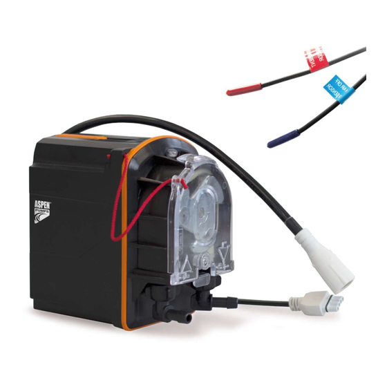
PERISTALTIC PRO PUMPS
FP3390 – PERI PRO AIR / FP3391 – PERI PRO
IN THE BOX
3m PVC hose
ID Ø6mm x OD Ø9mm
3m Power cable
(with plug & play connector)
IN THE BOX
3m PVC hose
ID Ø6mm x OD Ø9mm
3m Power cable
(with plug & play connector)
110VAC – 230VAC 50/60Hz
15L/hr
12m
3m
21 dB(A)
110 VAC – 230 VAC, 50/60Hz
Continuous
II Appliance
Up to 20kW (68k Btu/h)
6mm ID
6mm ID
IP24 – Splash proof
40°C / 104°F
40°C / 104°F
INSTALLATION
Wall bracket
Inlet hose adaptor
Inlet hose
Wall bracket
Float sensor
Float sensor
breather tube
Inlet hose
PERFORMANCE
15
12
9
6
3
110VAC-230VAC
50/60Hz
0
1
+
PERI PRO AIR (FP3390)
M8 Stud fixing
Ties x 6
PERI PRO + (FP3391)
M8 Stud fixing
Ties x 6
110VAC – 230VAC 50/60Hz
5
10
LITRES PER HOUR
EN
3m Air sensor cable
(with plug & play connector)
3m Float sensor cable
(with plug & play connector)
Max. rec. head 12m
15
20
Advertisement
Table of Contents

Subscribe to Our Youtube Channel
Related Manuals for Aspen Pumps PERI PRO AIR


Summary of Contents for Aspen Pumps PERI PRO AIR
- Page 1 PERISTALTIC PRO PUMPS INSTALLATION FP3390 – PERI PRO AIR / FP3391 – PERI PRO IN THE BOX PERI PRO AIR (FP3390) 3m PVC hose Wall bracket M8 Stud fixing 3m Air sensor cable ID Ø6mm x OD Ø9mm (with plug & play connector)
-
Page 2: Installation Introduction
When a differential temperature of greater than 5ºC Note: Typical dimensions shown apply to Peri Pro & Peri Pro Air models. Example shown is Peri Pro occurs between the two sensors, the pump will operate. -
Page 3: Installation
POMPES PÉRISTALTIQUES PRO INSTALLATION FP3390 – PERI PRO AIR / FP3391 – PERI PRO DANS LA BOÎTE PERI PRO AIR (FP3390) Tuyau PVC de 3 m Support mural Fixation pour tige filetée M8 Câble du capteur d’air de 3 m ID Ø6 mm x OD Ø9 mm... - Page 4 L’exemple illustré est celui du Peri Pro apparaît entre les deux sondes, la pompe fonctionne. Comment régler la vitesse sur le Peri Pro Air RECHERCHE DE PANNES Lors de la mise sous tension, appuyez sur le bouton de test situé à l’arrière de la pompe et maintenez-le enfoncé...
-
Page 5: Spezifikationen
PERISTALTISCHE PRO-PUMPEN INSTALLATION FP3390 – PERI PRO AIR / FP3391 – PERI PRO IN DER KISTE PERI PRO AIR (FP3390) 3m PVC-Schlauch Wandhalterung M8 Bolzenbefestigung 3m Luftsensorkabel ID Ø6 mm x OD Ø9 mm (mit Plug & Play-Anschluss) 3m Stromkabel Adapter für... -
Page 6: Fehlerfindung
Innengerät Tropfschale Pumpengehäuse darf nicht geöffnet werden und enthält keine vor Ort zu wartenden Teile. Hinweis: Die gezeigten typischen Abmessungen gelten für die Modelle Peri Pro+ und Peri Pro Air. Das gezeigte Peri Pro Air Beispiel ist Peri Pro Der rote (heiße) Sensor wird am Lufteinlass der Klimaanlage angebracht, der blaue (kalte) Sensor am Luftauslass der Klimaanlage. - Page 8 +44 (0)1323 848842 sales@aspenpumps.com Aspen Pumps, Apex Way, Hailsham, East Sussex, BN27 3WA, UK • Information correct at time of going to press • Informations correctes au moment de la publication • Información correcta en el momento de enviarse a imprenta •...
Need help?
Do you have a question about the PERI PRO AIR and is the answer not in the manual?
Questions and answers