Table of Contents
Advertisement
Quick Links
Advertisement
Table of Contents

Related Manuals for Microcyber G1013


Summary of Contents for Microcyber G1013
- Page 1 G1013 HART to FF Gateway User Manual Microcyber Corporation...
-
Page 2: Table Of Contents
Default Communication Parameter................14 Supported HART Command..................14 Appendix G1013 Selection Example..................15 Table of Contents Figure 1.1 G1013 HART to FF Gateway..................1 Figure 1.2 Dimension (Unit: mm)....................1 Figure 1.3 Structure........................2 Figure 2.1 Wiring......................... 3 Figure 2.2 Hardware Switch......................4 Figure 3.1 System Connection.....................5... - Page 3 Since variance cannot be precluded entirely, we cannot guarantee full consistency. However, the information in this publication is reviewed regularly and any necessary corrections are included in subsequent editions. Microcyber Corporation 2015 The technical data may change at any time.
-
Page 4: Overview
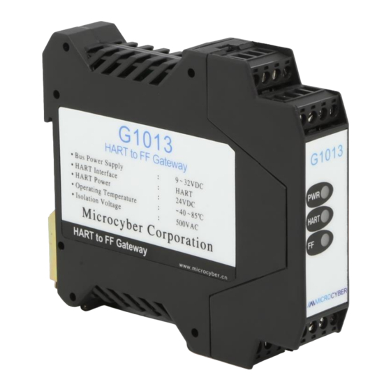
HART protocol and FF protocol. As HART master, G1013 HART to FF Gateway communicates with HART slave via HART interface, it can convert dynamic variables in the device to FF device variables output. G1013 HART to FF Gateway is shown as Figure 1.1. -
Page 5: Structure
1.2 Structure Figure 1.3 Structure 1 Upside Housing 2 Bottom Housing 3 FF Communication Board 4 HART Bottom Board 5 Terminal HART to FF Gateway | G1013 | Page Email | fang.siqi@microcyber.cn... -
Page 6: Installation
24V+ 24V- Figure 2.1 Wiring G1013 HART to FF Gateway is powered by FF bus, and the HART part shall be with 24V external powered. The recommended is TP cable, and it shall improve device’s anti- electromagnetic interference ability. 2.2 DIP Switch Setting There is a 3-bit DIP switch for G1013 HART to FF Gateway, shown as Figure 2.2. - Page 7 Figure 2.2 Hardware Switch HART to FF Gateway | G1013 | Page Email | fang.siqi@microcyber.cn...
-
Page 8: Working Principle
FF bus communication. HART interface board is only used in G1013, for signal isolation, signal convert, FF/PA communication module power, and HART device power, etc. The working principle for G1013 is shown in Figure 3.2. G1013... -
Page 9: Gateway Configuration
Figure 4.2 FF Bus Connection 4.2 Function Block Description For default configuration for G1013, there is 1 RES function block complying with FF specification, 1 HART transducer block (HART_TB), 4 AI function blocks and 1 PID function block. AI function blocks support 16 channels, and 16 channels and 4 devices’ PV, SV, TV and QV are corresponding. -
Page 10: Hart Transducer Block Configuration Parameters
POLLING_ADDRESS USIGN8 HART slave polling address, range 0~63 UNIVERSAL_REVISION USIGN8 HART protocol revision TRANSMITTER_REVISION USIGN8 Transmitter revision SOFTWARE_REVISION USIGN8 Software revision HARDWARE_REVISION USIGN8 Hardware revision DEVICE_ID USIGN32 Device ID HART to FF Gateway | G1013 | Page Email | fang.siqi@microcyber.cn... -
Page 11: Hart Transducer Block Configuration Example
FUNCT USIGN8 Linearization 4.4 HART Transducer Block Configuration Example Following is an example with NI- Configurator of how to configure HART transducer block. Configuration for Number of HART devices HART to FF Gateway | G1013 | Page Email | fang.siqi@microcyber.cn... - Page 12 If the communication is successful, Device 1 Init Failed shall disappear in Err Look Result. Meanwhile all the parameters in HART LOC PARM1 shall refresh, and PV, SV, TV and QV shall be read from HART device automatically. HART to FF Gateway | G1013 | Page Email | fang.siqi@microcyber.cn...
-
Page 13: Hart Transducer Block List
Type Number of NUMBER_DEVICE Unsigned8 HART Devices Status ERR_LOOK_RESULT Bitstring(32) Indication HART HART_LOC_PARM1 DS-272 Device Parameter HART_PV1 DS-65 PV_LOC_PARM1 DS-273 D/RO Parameter HART_SV1 DS-65 SV_UNIT1 Unsigned16 D/RO SV Unit HART to FF Gateway | G1013 | Page Email | fang.siqi@microcyber.cn... - Page 14 Unsigned16 D/RO TV Unit HART_QV3 DS-65 QV_UNIT3 Unsigned16 D/RO QV Unit HART HART_LOC_PARM4 DS-272 Device Parameter HART_PV4 DS-65 PV_LOC_PARM4 DS-273 D/RO Parameter HART_SV4 DS-65 SV_UNIT4 Unsigned16 D/RO SV Unit HART to FF Gateway | G1013 | Page Email | fang.siqi@microcyber.cn...
- Page 15 Device 4 No Use Device 2 Init Failed Device 4 Init Failed Device 2 Comm Failed Device 4 Comm Failed Reserved Reserved Reserved Reserved Reserved Reserved Reserved Reserved Reserved Reserved HART to FF Gateway | G1013 | Page Email | fang.siqi@microcyber.cn...
-
Page 16: Maintenance
Power failure connection HART Power Yellow Contact technical Internal failure support Daily maintenance is only for device cleansing. Failure maintenance: Please return to factory if there is failure. HART to FF Gateway | G1013 | Page Email | fang.siqi@microcyber.cn... -
Page 17: Technical Specification
Read dynamic variable and PV current Read device information Read device mark, description and date Read PV sensor information Read device primary variables’ information Read last assembly line number HART to FF Gateway | G1013 | Page Email | fang.siqi@microcyber.cn... -
Page 18: Appendix G1013 Selection Example
Appendix G1013 Selection Example GW-HART-FF G1013 HART to FF Gateway Code Hardware Interface FSK(1200bps) Code Software Interface HART Master GW-HART-FF M ——Selection Example HART to FF Gateway | G1013 | Page Email | fang.siqi@microcyber.cn... - Page 19 YOUR FIELDBUS EXPERT CONTACT INFORMATION Address: 17-8 Wensu Street, Hunnan New District, Shenyang, China Website: www.microcyber-fieldbus.com Phone: +86-24-31217278/+86-24-31217280 Fax: +86-24-31217338 Email: fang.siqi@microcyber.cn HART to FF Gateway | G1013 | Page Email | fang.siqi@microcyber.cn...
Need help?
Do you have a question about the G1013 and is the answer not in the manual?
Questions and answers