Table of Contents
Advertisement
Quick Links
Advertisement
Table of Contents

Related Manuals for Microcyber G0310


Summary of Contents for Microcyber G0310
- Page 1 G0310 Modbus to HART gateway User Manual...
- Page 2 Warning Please don’t take off/install gateway at random. Please check if the power of temperature board set meets the power request in the User Manual. ~ I ~...
- Page 3 Microcyber undertakes a number of national scientific and technical key task and “863” project, and has Liaoning Province networked control systems engineering research center. The company successfully developed the FF H1...
-
Page 4: Table Of Contents
Contents Chapter 1 Overview................................1 1.1 Dimension..................................1 1.2 Structure..................................1 Chapter 2 Installation................................2 2.1 Wiring....................................2 2.2 Jumper configuration..............................2 2.3 Internal load resistance..............................3 2.4 Recalibration................................. 3 Chapter 3 Working Principle..............................4 Chapter 4 Menu Tree................................5 Chapter 5 Transmitter Configuration............................6 5.1 Topological Connection..............................6... - Page 5 Chapter 8 Technical Specification............................35 Chapter 9 Appendix1 G0310 MODBUS to HART Gateway Model Selection................ 36 ~ IV ~...
-
Page 6: Chapter 1 Overview
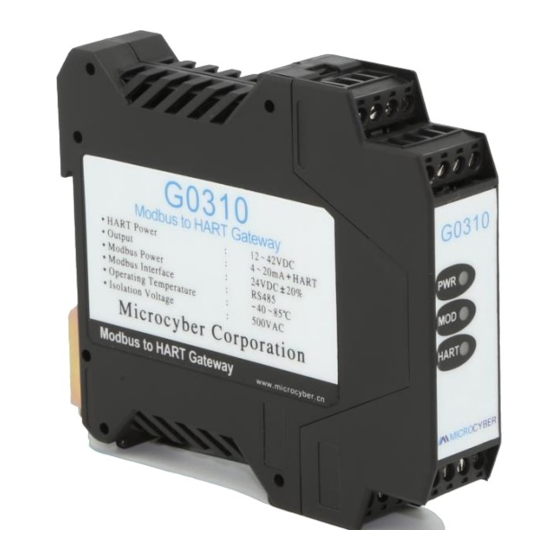
Chapter 1 Overview G0310 Modbus to HART Gateway, designed by Microcyber Corporation is a gateway device for Modbus-RTU protocol and HART protocol. As Modbus master, G0310 Modbus to HART Gateway communicates with devices that have Modbus-RTU communication function via RS485 interface. It can convert device data to HART device variables output, and it also supports 4~20mAcurrent output. -
Page 7: Chapter 2 Installation
Figure 2.2 G0310 MODBUS to HART gateway connection diagram Jumper configuration G0310 MODBUS to HART Gateway has 2 jumpers, as shown on Figure 2.3. the left one is failure warning current setting and the right one is configuration protection setting jumper. -
Page 8: Internal Load Resistance
Internal load resistance to replace resistance in Figure 2.2. Then HART Modem can connect on terminal 13 and 14. Recalibration Users can make a recalibration on G0310 Modbus to HART gateway at test room or installation site before it was put into application. The operation process is shown as in the Figure 2.4. maintenance... -
Page 9: Chapter 3 Working Principle
G0310 MODBUS to HART Gateway supports 4 dynamic variables, 6 device variables.Via MODBUS register, the data selected by MODBUS device is configured to device variables of G0310 MODBUS to HART Gateway, and then, it enters the mapping from device variable to dynamic variable, as the device output, supporting 4~20mA analog signal output.G0310 MODBUS to HART Gateway functional block diagram is shown as Figure 3.1 :... -
Page 10: Chapter 4 Menu Tree
1 damping value 4 validation 2 sensor info 2 unit 5 stop bits 3 main variable output 3 URV G0310 setting 6 CRC byte order 4 PV setting 4 LRV 1 basic info 7 interframe space PV setting 5 transfer function... -
Page 11: Chapter 5 Transmitter Configuration
Chapter 5 Transmitter Configuration Topological Connection The connection mode of HART transmitters can be divided into point-to-point connection and multi-point connection. point to point connection Figure 5.1 HART Point-to-point connection Features : 1) It can be connected to the upper control system through the AI input module or HART communication device ;... -
Page 12: Configuration Tool
Configuration tool 5.2.1 Installation and activation The PC software of G0310 is design and development by Microcybe, the installation method is shown as follow: First double-click to install the setup as shown in the Figure 5.3: Figure 5.3 setup Click “next” to the installation page as shown in the Figure 5.4: Figure 5.4 installation... - Page 13 Figure 5.6 installation Figure 5.7 installed The HARTMPT icon will appear on the desktop after the installation is complete as shown in the Figure5.8: Figure 5.8 PC software After the installation is complete, it goes directly to the system as shown in the Figure 5.9:...
-
Page 14: Introduction Of Main
Figure 5.9 system interface 5.2.2 Introduction of main page features The configuration tool can be started by executing the shortcut of this software on the desktop or in the start menu. After the configuration tool is started, the interface and the main windows are shown in Figure 5.10. - Page 15 View menus also feature display and hide alarm windows and send commands. Device (D) By "on-line "," stop on-line ", you can search any online devices in the network. To use this feature, cancel "Display Online Only ".
-
Page 16: Basic Operations
Figure 5.12 16offline devices Tabular View Different tabs appear depending on the nodes selected by the network view. When the serial port node is selected, the device list and the main variable scan tab are displayed. When any device node is selected, the relevant tabs of the device are displayed, such as basic information, configuration information, sensor configuration, current calibration, and special commands. - Page 17 If the serial port setting fails, select again. Serial port setting failure, can not carry out communication operation. Device Scan Configuration tools only support user access to online devices, so you need to query which devices are currently online. Query methods can be divided into three categories: (1) Single node search: according to the polling address of the target device, find whether the specified device is online;...
- Page 18 +@+ the device polling address. iii. Send command Click “view” “send command” on the menu bar to view send commands and call out the send command window, as shown inFigure 5.16. By this function, users can send all supported HART general commands, general behavior commands, special commands.
-
Page 19: Device Operation
Device operation list of device The device list tab displays summary information for all searched online devices. for example: polling address, device label, vendor, device type, ex-factory date, etc. Method 1 to enter the Device List tab: After searching the online device, the default recovery displays the device list tab. - Page 20 Figure 5.19 Main variable monitoring tab iii. Basic Info Users can obtain and configure basic information about online devices. Method to access the Basic Information tab: (1) The left mouse button clicks on an online device in the network view, and the right tab view displays the tabs associated with the device.
- Page 21 Manufacturer Display manufacturer name Type Display device type equipment Display Equipment ID Number equipment Long address Display device length address Version Display version information such as software, information hardware versions, etc As shown in the above table, the first six device information is modifiable information.
- Page 22 Serial Sensor serial number, writable number Upper limit Upper limit of sensor measurement range Lower limit Lower limit of sensor measurement range Minimum The sensor allows the minimum range to be span Configuration information mainly includes three parts: output variable, PV setting and range calibration.
- Page 23 Figure 5.22 Current calibration tab The current calibration steps are as follows: (1) Connection circuit, need to be connected to the device output circuit in series with more than five and a half precision ammeter; (2) Set the device's polling address to 0, refer to basic information configuration, if the polling address is 0, skip this step;...
-
Page 24: Gateway Parameter Setting
PV value, current value, percentage and SV value, respectively. Method to go to the refresh device tab: (1) Left-click on an online device in the network view, and the right tab view displays the tabs associated with the device. -
Page 25: Coil Calibration
Figure 5.24 Gateway Configuration (3) Then find the "detailed settings"->"operation mode", there are two operation modes, one is "configuration mode" and the other is "operation mode ". “Configuration mode” can set the screen so option, “operation mode” can only set the “factory reset”. -
Page 26: Register Calibration
Figure 5.27 Read coil value input Then click the "OK" and the system prompts "read coil successfully ". Figure 5.28 read coil success prompt 5.5.3 Register Calibration Register read and write, the user can select "calibration "->" register" box, read and write separate registers. -
Page 27: Save To Factory Settings
Figure 5.31 Restore to factory default settings After selecting “Yes” in the drop-down box, click OK. Figure 5.32 Restore to factory default settings selection The system prompts "set up successfully ", then clicks OK to complete the operation. Figure 5.33 Returns to factory default settings prompt 5.5.4.2... -
Page 28: Reset To Factory Settings
Figure 5.35 Save to factory settings selection The system prompts "set up successfully", then clicks OK to complete the operation. Figure 5.36 Save to factory settings prompt 5.5.4.3 Reset to factory settings Click the "Calibration"->"restore factory settings"->"restore to factory settings", pop up "restore to factory settings"... -
Page 29: Device Variable Assignment
Figure 5.39 Reset to factory settings prompt 5.5.4.4 Device variable assignment Setting dynamic variable parameter assignment is to set the mapping relationship between device variable and dynamic variable. There are 6 device variables in the device, which can be mapped to 4 dynamic variables according to demand. -
Page 30: Modbus Variable Configuration
Figure 5.42 Save the device variable value 5.5.5 Modbus variable configuration Modbus communication parameters are configured according to Modbus specific communication parameters. 5.5.5.1 Address locate the "detailed design"->"Modbus variable"-> the input box corresponding to"address", as shown in Figure 5.43 Figure 5.43 Modbus Address settings... -
Page 31: Data Bits
5.5.5.3 Data bits Select "Detailed Design"->" Modbus variable "-> the drop-down box corresponding to"data bit", select the supported data bit number of 7 or 8 bits, as shown in Figure 5.45 Figure 5.45 Modbus Data Bit Selection Select the value that needs to be modified, then click the apply button to save the modified value. -
Page 32: Time Frame Interval
Figure 5.48 Modbus CRC byte order selection Select the value that needs to be modified, then click the apply to save the modified value. 5.5.5.7 Time frame interval Select "Detailed Design"->"Modbus variable"-> the drop-down box corresponding to"frame interval time", the interval time range is 4~10, as shown in Figure 5.49 Figure 5.49 Modbus Number of frame intervals selected... -
Page 33: Pv Range Operation Mode
Select "detailed Design"->"PV range"-in the drop-down box corresponding to"PV range source", which includes local and remote sources, as shown in Figure 5.52 Figure 5.52 PV Range Source Selection Select the value that needs to be modified, then click apply to save the modified value. -
Page 34: Unit
Figure 5.56 Type Selection Select the value that needs to be modified, then click apply to save the modified value. 5.5.8.2 Unit select "Detailed Design"->"Sensor"-> drop-down box corresponding to"Unit", as shown in Figure 5.57 Figure 5.57 Unit selection Select the value that needs to be modified, then click apply to save the modified value. -
Page 35: Range Limit
Figure 5.60 Selection of the minimum span Enter the modified value, then click apply to save the modified value. 5.5.8.6 Range limit Select the "detailed design"->"sensor"-> the drop-down box corresponding to the"range limit", as shown in Figure 5.61 Figure 5.61 Upper Range Selection Enter the modified value, then click apply to save the modified value. -
Page 36: Modbus Functional Code
Figure 5.63 Default unit selection Select the value that needs to be modified, then click apply to save the modified value. 5.5.8.9 Modbus functional code Select "Detailed Design"->"Sensor"-> the drop-down box corresponding to"Modbus function Code". Figure 5.64 Modbus Functional code selection Select the value that needs to be modified, then click the apply button to save the modified value. -
Page 37: Range Upper Limit Register Address
Figure 5.67 Scale Factor Selection Enter the modified value, then click the apply button to save the modified value. 5.5.8.13 Range Upper Limit Register Address Select > drop-down box corresponding to "detailed design"-"sensor"->"range upper limit register address", as shown in Figure 5.68 Figure 5.68 Address Selection of Range Upper Limit Register... -
Page 38: Chapter 6 Quick Configuration
Chapter 6 Quick configuration Step 1 set "Operation mode" to "Configuration mode ". See subsection 5.5.1. Step 2 set the "device variable assignment" parameter, set the mapping relationship between the device variable and the dynamic variable, the device has 6 device variables, which can be mapped to 4 dynamic variables according to the requirements. -
Page 39: Chapter 7 Maintenance
Chapter 7 Maintenance Simple Maintenance Phenomena Reason Solution a. Power failure a. Repair the power Current output is 0 b. Wire open circuit b. Check the wire Output current beyond Failure between MODBUS device and Check MODBUS communication... - Page 40 Chapter 8 Technical Specification a) Basic parameter Measurement Object Modbus RTU slave device Power 12 ~ 42VDC Bus Protocol 2-wire , 4 ~ 20mA+HART 0 ~ 1500Ω ( 4 ~ 20mA ) Load resistance 230 ~ 1100Ω ( HART communication )...
- Page 41 Chapter 9 Appendix1 G0310 MODBUS to HART Gateway Model Selection G0310 Modbus to HART Gateway Code code Hardware interface Type R4( could be omitted) RS485 Selection Code code Software interface List MR M (could be omitted) Modbus RTU Master G0310-(R4-MRM)—— Selection Example...
- Page 42 M I C R O C Y B E R C O R P O R AT I O N Microcyber Corporation Http://www.microcyber.cn/en Add : 17-8 Wensu Street, Hunnan New District, Shenyang, China 110179 Tel : 0086-24-31217278 / 31217280 Fax : 0086-24-31217293 Email : sales@microcyber.cn...
Need help?
Do you have a question about the G0310 and is the answer not in the manual?
Questions and answers