Table of Contents
Advertisement
Quick Links
Advertisement
Table of Contents

Related Manuals for Microcyber G1003


Summary of Contents for Microcyber G1003
- Page 1 G1003 HART to Modbus Gateway User Manual Microcyber Corporation...
- Page 2 Since variance cannot be precluded entirely, we cannot guarantee full consistency. However, the information in this publication is reviewed regularly and any necessary corrections are included in subsequent editions. Microcyber Corporation 2015 The technical data may change at any time.
-
Page 3: Table Of Contents
Content CHAPTER 1 OVERVIEW ........................... 1 1.1 O ............................1 UTLINE TRUCTURE 1.1.1 Gateway Dimension Figure ......................1 1.1.2 Gateway Structure Figure .......................2 CHAPTER 2 INSTALLATION ........................3 2.1 D ..........................3 NSTALLATION 2.2 G ........................3 ATEWAY ARDWARE NTERFACE 2.2.1 HART Interface ..........................4 2.2.2 Gateway Power interface .......................4 2.2.3... - Page 4 4.2 O ....................16 VERVIEW OF ONFIGURATION OFTWARE 4.3 S ................18 OFTWARE ONFIGURATION AND ARDWARE ONNECION 4.4 B ................20 ASIC ARAMETER ONFIGURATION FOR ODBUS HANNEL 4.5 B HART C ................21 ASIC ARAMETER ONFIGURATION OF HANNEL 4.6 P HART C ................
-
Page 5: Chapter 1 Overview
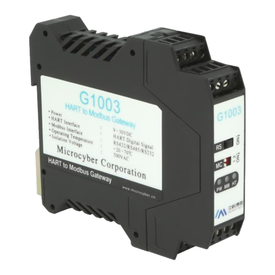
The gateway realizes protocol converting from HART to Modbus RTU / ASCII. Supporting to connect multi HART slave devices into Modbus network. In the gateway, HART terminal is master station, Modbus terminal is slave station. Figure 1 G1003 HART to Modbus Gateway Product Diagram 1.1 Outline Structure 1.1.1 Gateway Dimension Figure 114.5... -
Page 6: Gateway Structure Figure
1.1.2 Gateway Structure Figure Figure 3 Gateway Structrure Figure Teminal Bottom Housing Main Board Upside Housing - 2 -... -
Page 7: Chapter 2 Installation
Chapter 2 Installation 2.1 Din Rail Installation Press downward Pull upward Push Inward Pull downward Figure 4 Din Rail Installation Figure 2.2 Gateway Hardware Interface HART+ HART- Internal/external sampling resistor selection switch EARTH Gateway mode Terminal Introduction selection switch T-/B- T+/A+ EARTH Figure 5 Gateway Hardware Interface Figure... -
Page 8: Hart Interface
2.2.1 HART Interface Table 1 HART Interface Terminal Defination Name Usage HART+ Connect HART sampling resistor HART- Connect HART sampling resistor Not Connected Not Connected 2.2.2 Gateway Power interface Table 2 Power Interface Teminal Defination Name Usage Connect 9-30V DC power+ Connect 9-30V DC power- EARTH Protective earth terminal... -
Page 9: Internal /External Sampling Resistor Selection Switch (Rs)
Yellow Modbus sending indicator Yellow-green Green Modbus receiving indicator Yellow HART sending indicator Yellow-green Green HART receiving indicator 2.3 Typical Topologic Connection G1003 24VDC Power Supply 250Ω Neg(-) (1/4W) 250Ω HART+ Pos(+) 4~20mA HART- Loop powered – use external resistor Transmitter Figure 6 Loop Powered –... - Page 10 24VDC G1003 Power Supply Ω Neg(-) Pos(+) 4~20mA (1/4W) Ω HART+ HART- External Powered – Use External Resistor Transmitter Figure 7 External Powered – Use External Resistor 24VDC 4~20mA Power Supply G1003 Neg(-) 250Ω (1/4W) Pos(+) HART+ HART- Transmitter Loop Powered – Use External Resistor Figure 8 Loop Powered –...
- Page 11 G1003 24VDC Power Supply 250Ω Neg(-) (1/4W) 250Ω HART+ Pos(+) HART- Transmitter Note: To avoid internal resistor over current burn out, shall select external Transmitter resistor under multi- point connection mode. Loop Powered-Use External Resistor-Multi- point connection mode Transmitter Figure 9 Loop Powered – Use External Resistor– Multi-point Connection Mode...
-
Page 12: Chapter 3 Function Overview
Modbus gateway, easily realize the function that Modbus master station accesses to HART network data. Modbus Master Modbus Remote IO G1003 HART Slave Figure 11 Topology Connection for Gateway Application 3.1 Working Modes of the Gateway The HART to Modbus gateway has four working modes, respectively is normal working mode, HART modem mode, configuration mode and debugging mode. -
Page 13: Hart Modem Mode
3.1.2 HART Modem Mode The Gateway transfers all the data between HART master system and slave network by unvarnished transmission mode. The gateway may be completely used as HART modem. Modbus channel transmits data according to HART channel’s communication parameters (baud rate: 1200bps, 8-bit data bit, odd parity, 1-bit stop bit). -
Page 14: Summary Of Modbus Channel
slave device, the data will be temporarily stored into data input area inside the gateway; When the gateway needs to send a user configuration command to HART slave device, the data will be read from data output area inside the gateway. After the HART to Modbus gateway is powered on, it will send HART command 0 to query if the configured device is online, and set whether online mark of the corresponding device by judging whether there’s response from slave device. -
Page 15: Data Area Inside The Gateway
all occupy the Modbus channel, namely the three hardware interfaces can be connected at the same time, but cannot communicate at the same time. 3.4 Data Area inside the Gateway Internal data area of the HART to Modbus gateway is shared by HART channel and Modbus channel. -
Page 16: Partition Of Internal Data Area
3.4.2 Partition of Internal Data Area Partition of data area inside the HART to Modbus gateway is shown in Figure13: Function code: Data output area 0x03/0x06/0x10 Data input area Data Area Basic data of addr 0 HART slave device Function code:0x04 Basic data of addr 1 HART slave device Basic data of addr 2 HART slave device Basic data of addr 15 HART slave device... - Page 17 in the table below: Table 9 Basic Data Information of Each HART Slave Device Data Area Data Byte Description Data Resource Byte Offset Type Number Byte Auto-polling mode command status Produced by Gateway Byte Response Code (RC) HART response frame Byte Device status (DS) HART response frame...
-
Page 18: Self-Defined Hart Command List
60-61 Word Private label distributor code CMD0/CMD15 62-65 Float Primary variable (PV) CMD3 66-69 Float Secondary variable (SV) CMD3 70-73 Float Tertiary variable (TV) CMD3 74-77 Float Quaternary variable (QV) CMD3 78-81 Float Upper transducer limit CMD14 82-85 Float Lower transducer limit CMD14 86-89 Float... - Page 19 Data Output Area Frame Frame Write data head Frame Frame Read data head Data Input Area Figure 14 Data Input / Output Area Access When sending self-defined HART command package, the data of data domain is written by the user in data output area, and the user shall ensure its correctness. - 15 -...
-
Page 20: Chapter 4 Gateway Configuration
4.1 Install and Start Configuration Software Before configuring the HART to Modbus gateway, Modbus General Configuration tool must be installed (You can download the latest version from www.microcyber.cn/en). Then run file “Modbus General Configuration tool.exe”, following installation notes, you may install the software smoothly. - Page 21 Figure 15 Main Interface of Configuration Software ① Menu Bar File, the user executes menu "File"- >"Exit" or click close button at top right corner of the window, the configuration software will exit; Tool, include “Language Setting” function, support Chinese and English ...
-
Page 22: Software Configuration And Hardware Connecion
Figure 16 Device List Interface ④ Device Information Display manufacturer information ID, device type ID and protocol type, etc. ⑤ Parameter Area Display device configuration parameters by sort in the form of table, and can view and configure the gateway parameters through this parameter area. ⑥... - Page 23 Device with the left button with the left button, or use “Search All Devices” the list to search devices with the left button. (5) Until now, G1003 shall be shown in the tree list of “Host->COMx”at the left side of configuration software. Click G1003 with the left button, the configuration software shall read out gateway’s all the current configuration parameters, and show in the...
-
Page 24: Basic Parameter Configuration For Modbus Channel
Figure 19 Interface for G1003 On-line 4.4 Basic Parameter Configuration for Modbus Channel Here it describes basic paramete configuration for Modbus channel, and the paramaters are effetice when the gateway is working at mormal mode. Choose “Modbus Configuration” in “Parameter List” in the parameter zone of configuraiton software, and it will show current configuration of Modbus channel, as Figure 20. -
Page 25: Basic Parameter Configuration Of Hart Channel
Table 12 Modbus Configuration Parameter Description Parameter Name Parameter Description Baud Rate 300,600,1200,2400,4800,9600,19200,38400,57600,115200bps, optional 7 bits or 8 bits, optional (When the communication mode is set as RTU, 7 Data Bits bits is unmeaning.) Parity None, Even or Odd, optional. Stop Bits 1 bit or 2 bits, optional CRC Byte Order... -
Page 26: Parameter Configuration For Custom Hart Command
Choose HART network’s topology connection is point to point or Network Mode multi-drop mode. In point to point mode, gateway can only communicate with HART slave with address 0. Master Type Choose gateway to work as primary or secondary master. It is used to configure short address (polling address)of slave Short Addr List device in HART network, range is 0-15.And it has many options. -
Page 27: Address Automatic Mapping
choosing a command, the user may modfy the command property and uses “Modify”to finish it. “Delete”shall delete the selected command. And each added command shall have the same property: Custom HART command parameter’s description is shown as following: Table 14 Custom HART Command Parameter Description Parameter Name Parameter Description Current command index, range is 0-99;... -
Page 28: Address Conflict Detection
without conflict, according to use’s configuration type length in input output zone. Click to finish the automatic distribution. 4.6.2 Address Conflict Detection Through conflict detection function The user may check distribution status for all the configured commands’ input and output data in memory, to check if there is a conflict. Click to see Figure 23. -
Page 29: Excel Save Configuration Parameter
(2) Use a serial line (or 485/422 convert serial line)to connect gateway’s RS232 interface and PC serial port, and then power the gateway on, at this time, the gateway is under debugging mode. (3) Start configuration software, after G1003 is powered on, click to see memory display shown as Figure 24. -
Page 30: Library File Save Configuration Parameter
.xml file, shown as Figure 25. Figure 25 Library File Save Choose “HART” in the library type, and input the name G1003, and click “Save”, then G1003.xml file has beed added to HART index under the tree list in the left. - Page 31 Figure 26 Modbus Parameter Configuration Example HART configuration data is shown as Figure 27, and after the configuration, the user shall click “Download the current page parameters”. Figure 27 HART Parameter Configuration Example To configure 2 HART custom commands, command 2 and command 34: Command 2 is to read loop current value and range percentage and command 34 is to write damping value.
-
Page 32: Verificaion
HART commands and obtain device info with with slave address 0. 4.9.2 Verificaion The user shall connect a HART pressure transmitter to G1003’s HART interface, and connect RS232 (or RS485/RS422 via 485/422 to RS232 converter), shown as Figure 29. 24VDC... - Page 33 Figure 30 Memory Display Command 2 is “Read loop current and percent of range”, and there is only response data and no request data. The first 4 byte groups make up the floating current valve, and the last 4 byte groups make up the floating percentage. Command 34 is “Write PV damping value”...
-
Page 34: Chapter 5 Gateway Status
Chapter 5 Gateway Status Shown as Figure 31, click the configuration software tool bar’s gateway status monitor the user may check gateway’s current working status and if the slave device in HART network is on-line or not. Figure 31 Gateway Status Monitor The current working mode represents gateway’s present working mode, and the user may judge if the MC is at the requested position. -
Page 35: Chapter 6 Gateway Maintenance
Chapter 6 Gateway Maintenance Simple Maintenance Normal Abnormal Colour Reasons Solution Status Status Power failure Check power and connection Yellow Internal failure Contact technical support Check configuration Wrong gateway parameter, if there is HART configuration command in the configuration Yellow Gateway is under Flickering... -
Page 36: Chapter 7 Technical Specificaions
Chapter 7 Technical Specificaions 7.1 Performance Name Description Gateway Power 9~30VDC Modbus Interface RS-232/RS-422/RS485 HART Interface HART digital signal Consumption Interface Input ≥5KΩ Inpedance HART Interface Voltage 50VDC Insulation Value 500mVpp (500Ω) HART Output Amplitude Humidity Range (5~95)%RH Working Temperature -20℃~70℃... -
Page 37: Default Communication Parameter
Modbus Communication Support Modbus slave RTU and ASCII communication mode Mode Modbus Function Code 0x03/0x04/0x06/0x10 7.2 Default Communication Parameter Modbus Default Communication Parameter Normal working mode / HART Modem mode configuration mode debug mode Baud Rate 19200 1200 Date Bits Rarity Even Stop Bits... -
Page 38: Appendix A Gateway Memory And Register Description
Appendix A Gateway Memory and Register Description Corresponding Gateway Function Type Modbus register Usage description Register repair memory offset address InData 2000 ~ 6999 1000 ~ 3499 User defined HART command data input field, to cache response data from HART slave device 7000 3500 H State byte indicating if Command 0,3,13,14,15 is sent successfully... - Page 39 32 bit Floating point 0x42 0x01 0x47 0xAE data (32.32) When a HART slave station device that connected with G1003’s HART interface off-line (power down), G1003 will keep the latest HART slave station device information before power down. - 35 -...
-
Page 40: Appendix B Hart Protocl
Appendix B HART Protocl HART protocol, proposed by Rosemount, is a kind of communication protocol used between intelligent instrument and control cabnet device. It’s a transitional protocol from 4~20mA analogue signal to digital signal. To overlay a digital signal on 4~20mA analogue signal, the original analogue signal is still valid, and they two will not affect each other. - Page 41 field end) HART application layer includes three kinds of HART command. It’s used to operate data, including universal command, common command and special command. HART universal command is introduced as below: Command 0: Read Unique Identifier Request Data Bytes Byte Format Description...
- Page 42 Command 1: Read Primary Variable Request Data Bytes Byte Format Description None Response Data Bytes Byte Format Description Enum Primary Variable Units Float Primary Variable Command 2: Read Loop Current and Percent of Range Request Data Bytes Byte Format Description None...
- Page 43 Enum Quaternary Variable Units Code 20-23 Float Quaternary Variable Command 4: Reserved Command 5: Reserved Command 6: Write Polling Address, that is Device Short Address Request Data Bytes Byte Format Description Unsigned-8 Polling Address of Device Enum Loop Current Mode Response Data Bytes Byte...
- Page 44 Enum Tertiary Variable Classification Enum Quaternary Variable Classification Command 9:Read Device Variables with Status Request Data Bytes Byte Format Description Unsigned-8 Slot 0: Device Variable Code Unsigned-8 Slot 1: Device Variable Code Unsigned-8 Slot 2: Device Variable Code Unsigned-8 Slot 3: Device Variable Code Unsigned-8 Slot 4: Device Variable Code...
- Page 45 Enum Slot 3: Units Code 28-31 Float Slot 3: Device Variable Value Bits Slot 3: Device Variable Status Unsigned-8 Slot 4: Device Variable Code Enum Slot 4: Device Variable Classification Enum Slot 4: Units Code 36-39 Float Slot 4: Device Variable Value Bits Slot 4: Device Variable Status Unsigned-8...
- Page 46 Command 12:Read Message Request Data Bytes Byte Format Description None Response Data Bytes Byte Format Description 0-23 Packed Message Command 13:Read Tag, Descriptor, Date Request Data Bytes Byte Format Description None Response Data Bytes Byte Format Description Packed 6-17 Packed Descriptor...
- Page 47 Command 15:Read Device Information Request Data Bytes Byte Format Description None Response Data Bytes Byte Format Description Enum PV Alarm Selection Code Enum PV Transfer Function Code Enum PV Upper and Lower Range Values Units Code Float PV Upper Range Value(URV) 7-10 Float PV Lower Range Value(LRV)...
- Page 48 Command 18:Write Tag, Descriptor, Date Request Data Bytes Byte Format Description Packed 6-17 Packed Descriptor 18-20 Date Date code Response Data Bytes Byte Format Description Packed 6-17 Packed Descriptor 18-20 Date Date code Command 19:Write Final Assembly Number Request Data Bytes Byte Format...
- Page 49 Response Data Bytes Byte Format Description Same as Command 0 Read Unique Identifier. Command 22:Write Long Tag Request Data Bytes Byte Format Description 0-31 Latin-1 Long Tag Response Data Bytes Byte Format Description 0-31 Latin-1 Long Tag Command 38:Reset Configuration Changed Flag Request Data Bytes Byte Format...
- Page 50 Response Data Bytes Byte Format Description Bits or Enum Device-Specific Status Bits Extended Device Status Bits Device Operating Mode,0x00 Bits Standardized Status 0 Bits Standardized Status 1 Bits Analog Channel Saturated Bits Standardized Status 2 Bits Standardized Status 3 Bits Analog Channel Fixed 14-24 Bits or Enum...
-
Page 51: Appendix C Modbus Protocl
Appendix C Modbus Protocl Statement: The objective of this document is only to present the MODBUS protocol to users. 1) Modbus protocol is mainly used between controllers. By Modbus, two controllers can communicate with each other or they can rely on network (e.g. Ethernet) to communicate with other devices. - Page 52 3) Modbus defines two kinds of Character transfer mode: ASCII mode、 RTU (binary system) mode, and they cannot be mix-up.This product is suitable for these two modes. Features RTU mode ASCII mode Coding binary system ASCII(Print character:0-9,a-z,A-Z) Each character start bit:1BIT start bit:1BIT...
- Page 53 Microcyber Corporation Add: 17-8 Wensu Street, Hunnan New District, Shenyang, China 110179 Tel: 86-24-31217278 Fax: 86-24-31217293 E-mail: international@microcyber.cn Website: www.microcyber.cn...
Need help?
Do you have a question about the G1003 and is the answer not in the manual?
Questions and answers