
Subscribe to Our Youtube Channel
Related Manuals for Weq ADL500


Summary of Contents for Weq ADL500
- Page 1 Motors | Automation | Energy | Transmission & Distribution | Coatings Vector inverter for lifts with synchronous/asynchronous motors ADL500 Fast start up guide Language: English...
-
Page 2: Information About This Manual
Information about this manual The ADL500 FAST (Fast start up guide) is a handy-sized manual for mechanical installation, electrical connection and fast start-up. Before installing, connecting and commissioning, carefully read the relevant Safety Instructions in the ADL500 HW + QS manual. -
Page 3: Table Of Contents
5.2.4 +24V supply connection ..................................18 5.2.5 Safety STO connection (SFTY-STO) ..............................19 5.2.6 Led ........................................19 5.3 Typical connection diagram ............................... 20 6 - Use of the optional keypad (KB-ADL500) ................22 6.1 Description ..................................22 6.1.1 Membrane keypad ....................................22 6.1.2 Meaning of LEDs ....................................22 6.2 Navigating with the optional keypad .......................... -
Page 4: Safety Precautions
The following instructions are provided for your safety and as a means of preventing damage to the product or compo- nents in the machines connected. This section lists instructions, which apply generally when handling electrical drives. Specific instructions that apply to particular actions are listed at the beginning of each chapters. ADL500 • Quick installation guide... -
Page 5: General Warnings
Risque d’incendies et d’explosions: L’utilisation des drives dans des zônes à risques (présence de vapeurs ou de poussières inflammables), peut provoquer des incendies ou des explosions. Les drives doivent être installés loin des zônes dangeureuses, et équipés de moteurs appropriés. ADL500 • Quick installation guide... -
Page 6: Instruction For Compliance With Ul Mark (Ul Requirements), U.s. And Canadian Electrical Codes
Short circuit ratings ADL500 inverters must be connected to a mains capable of supplying a symmetrical short-circuit power of less than or equal to “xxxx A rms. The values of the “xxxx” A rms short-circuit current, in accordance with UL requirements ( ASME17.5/CSA B44.1 ), for each motor power rating (Pn mot in the manual) are shown in the table below. -
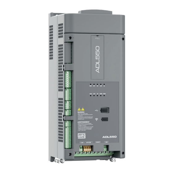
Page 7: Product Identification
• EFC application • hardware revision The code can be read by smartphones using dedicated applications or with specific industrial readers. I.e.: S9DL5565. ADL550-2150-XBL-F-4-EMS. 41GE038956 - Fw. 222 210 Appl. EFC 2.2.0 REV. HW A1 ADL500 • Quick installation guide... -
Page 8: Specification
Frequency range ����������������������� ± 2000 Hz Max frequency ������������������������ Flux vector CL control with feedback and brushless: 300Hz, FVOL: 150 Hz, VF: 600 Hz Min frequency ������������������������ 0 Hz (*) referred to Full scale speed, PAR:680. ADL500 • Quick installation guide... -
Page 9: Torque Control
Connection to IT Networks or Regenerative ��� only on request (*), please contact the WEG Customer Service. Choke ������������������������������� Sizes 1...2: Optional (DC or AC) Note! See chapter "5.2 Input chokes" on ADL500 HW+QS manual for THD values in accordance with EN 12015 and for selection of external inductances. Input Overvoltage... -
Page 10: Output Electrical Data
E.g.: Altitude 2000 m, Kalt = 1.2% * 10 = 12% derating; In derated = (100 - 12) % = 88 % In 3.6.1 Derating values in overload condition In overload conditions the output current DO NOT depends on the output frequency, as shown in the figure below. Figure 3.6.1: Ratio between overload/output frequency (ADL500-...-4) ADL550, sizes 1...3 ADL510/ADL530, sizes 1-3... -
Page 11: Kt: Ambient Temperature Reduction Factor
3.7 Voltage level of the inverter for safe operations The minimum time between the moment in which an ADL500 inverter is disabled from the mains and that in which an operator can operate on internal parts of the inverter, without the danger of electric shock, is 5 minutes. -
Page 12: Weights And Dimensions
12.1 ADL550-1... Figure 3.10.2:Size 2 dimensions 5.25 (1:1) (1:1) Dimensions: Width x Height x Depth Weight Sizes (mm) (inches) (kg) (lbs) ADL510-2... ADL530-2... 162 x 390 x 151 6.38 x 15.35 x 5.94 15.4 ADL550-2... ADL500 • Quick installation guide... -
Page 13: Mechanical Installation
����������������������� 25 mm 25 mm ( 0.98” ) 150 mm ( 6" ) 25 mm ( 0.98 ” ) 150 mm ( 6" ) 25 mm ( 0.98” ) 25 mm ( 0.98” ) ADL500 • Quick installation guide... -
Page 14: Fastening Positions
Recommended screws for fastening Size 1 (ADL5...-1...) 4 x M5 x 12 mm screws + Grover (spring-lock) washer + flat washer Size 2 (ADL5...-2...) 4 x M5 x 12 mm screws + Grover (spring-lock) washer + flat washer ADL500 • Quick installation guide... -
Page 15: Location And Identification Of Terminals And Leds
STO Safety terminals "5.2.5 Safety STO connection (SFTY-STO)" on page 19 (04) ETH-PC RJ45 terminal, Ethernet port (100 Mbit/s) "7.4 ETH-PC Ethernet Interface (RJ45 connector)" on ADL500 HW+QS manual (05) CANopen 417 Lift terminals "7.5 CAN interface" on ADL500 HW+QS manual (06) -
Page 16: Power Section
- Cod. S72684S13 (size 2) For compliance with EN 12016: put the optional metal support KIT-PWR SHIELD ASSY (A) on bolts (B) and tighten the two nuts fully (C). Fasten the power cable shield to the omega sections (D). ADL500 • Quick installation guide... -
Page 17: Regulation Section
T2 terminal shield connection (recommended) (1) Secure the braided shielded cable to the omega at terminal T2 (in the case of reduced lateral space it is possible to use the GND PLATE KIT (2), code S72684G13). ADL500 • Quick installation guide... -
Page 18: Feedback Connection
KIT (2), code S72684G13). Encoders provide motor speed and position feedback. The regulation algorithms in the ADL500 drive are capable of controlling asynchronous and permanent magnet synchronous (brushless) motors. With asynchronous motors the regulation algorithm may or may not use the speed measurement obtained from the encoder reading. -
Page 19: Safety Sto Connection (Sfty-Sto)
Colour Meaning ADL510 ADL530 ADL550 Yellow Braking Yellow Contactor closing command status Green Enable Current limit Generic alarm Green CAN 1 S-BY Yellow Stand-by Green Direction up DOWN Green Direction down Green Power Supply ON ADL500 • Quick installation guide... -
Page 20: Typical Connection Diagram
OPTIONAL AC CHOKE L1 OPTIONAL KEYPAD ETH-PC WIFI BRAKING RESISTOR OPTIONAL OPTIONAL POWER GEFRAN ADL530 SECTION DC CHOKE DIGITAL OUTPUT (ADL550 4 TO 22KW) XE-XER DIGITAL INPUT BRAKE DOOR DRIVE OK CONTACTOR CONTACTOR K31M K31M ADL500 • Quick installation guide... - Page 21 SAFETY CHAIN OPTIONAL AC CHOKE L1 OPTIONAL KEYPAD ETH-PC BRAKING RESISTOR OPTIONAL OPTIONAL POWER GEFRAN ADL510 SECTION DC CHOKE DIGITAL OUTPUT (ADL550 4 TO 22KW) XE-XER DIGITAL INPUT DOOR BRAKE DRIVE OK CONTACTOR CONTACTOR K31M K31M ADL500 • Quick installation guide...
-
Page 22: Use Of The Optional Keypad (Kb-Adl500)
6 - Use of the optional keypad (KB-ADL500) This section describes the optional KB-ADL500 programming keypad (cod. S5P11T) and how to use it (display and programming parameters). Note ! For the connetion refer to section "7.6 Optional Keypad interface (RJ45 connector)" on ADL500 HW+QS manual. -
Page 23: Navigating With The Optional Keypad
Input value too high the value entered too high Input value too low the value entered too low Out of range attempt to insert a value outside the min. and max. limits ADL500 • Quick installation guide... -
Page 24: How To Save Parameters
6.6 Saving and recovery of new parameter settings on USB (ADL550 and ADL530 only). To save drive parameters on the memory USB: Menu CONFIG DRIVE, parameter Save to USB, PAR 596: ADL500 • Quick installation guide... - Page 25 ADL _ 0001.DAT Load from USB 04.02 DRIVE INFO Press E to execute 04.03 DRIVE CONFIG 04.04 ALARM CONFIG ADL _ 0000.DAT Load from USB Done ADL _ 0000.DAT ADL _ 0001.DAT ADL _ 0001.DAT ADL500 • Quick installation guide...
-
Page 26: Startup Wizard For Asynchronous Motor
To terminate the sequence of functions and return to the menu, press the ESC key. At the end of the sequence, once the parameters have been saved, if commissioning is successful, the main menu will return. ADL500 • Quick installation guide... - Page 27 Range: 230 ... 480V Rated voltage Def: 03 /09 PAR: 2002 Range: 1 ... 1500A Rated current 11.8 Def: 11.8 04 /09 PAR: 2004 Range: 10 ... 32000rpm Rated speed 1450 Def: 1450 ADL500 • Quick installation guide...
- Page 28 STARTUP WIZARD procedure are saved in a RAM memory to enable the drive to perform the necessary calculations. These data are lost if the device is switched off. To save the motor data follow the procedure described in step 9. At the end of the procedure proceed to next step. ADL500 • Quick installation guide...
- Page 29 11154 Range: 0 ... 100,000 Load wei g ht Def: 09 /09 PAR: 11156 Range: 0 ... 10000 Rope wei g ht Def: At the end of the procedure proceed to next step. ADL500 • Quick installation guide...
- Page 30 0.00 Hz 07 /08 PAR: 11032 Range: -10000 ... 10000 Multi speed 6 0.00 Hz Def: 0.00 Hz 08 /08 PAR: 11034 Range: -10000 ... 10000 Multi speed 7 0.00 Hz Def: 0.00 Hz ADL500 • Quick installation guide...
- Page 31 The calculated parameters are saved in a RAM memory to enable the drive to perform the necessary calculations. These data are lost if the device is switched off. To save the motor data follow the procedure described in step 7. ADL500 • Quick installation guide...
- Page 32 (1) Press the E key to start the save parameters procedure. (2) Press E to confirm (3) End of procedure (4) When the parameters have been saved correctly the drive displays this screen to show that the startup wizard is complete. ADL500 • Quick installation guide...
-
Page 33: Startup Wizard For Brushless Motors
Down=Next Available selections: (0) None (default), (1) Digital, (2) Sinus, 02 /07 PAR: 2132 (3) Sinus SINCOS, (4) Sinus ENDAT, Encoder mode ENDAT (5) Sinus BiSS, (6) Digital (7) BiSS, (8) Sinus SSI Value: ADL500 • Quick installation guide... - Page 34 Torque constant [Nm/a] : (KT) Ratio between the torque generated by the motor and the current required to supply it. Note ! When data entry is complete the Take parameters command is executed automatically (menu MOTOR DATA, PAR: 2020). The motor data entered during the ADL500 • Quick installation guide...
- Page 35 11154 Range: 0 ... 100,000 Load wei g ht Def: 09 /09 PAR: 11156 Range: 0 ... 10000 Rope wei g ht Def: At the end of the procedure proceed to next step. ADL500 • Quick installation guide...
- Page 36 MtlSpd S0 ACTIVE SPEED Multispeed 0, PAR 11020 Multispeed 1, PAR 11022 Multispeed 2, PAR 11024 Multispeed 3, PAR 11026 Multispeed 4, PAR 11028 Multispeed 5, PAR 11030 Multispeed 6, PAR 11032 Multispeed 7, PAR 11034 ADL500 • Quick installation guide...
- Page 37 To save the new parameter settings, so that they are maintained also after power-off, proceed as follows: 01 /01 01 /01 STARTUP WIZARD PAR: PAR: Save parameters Save parameters Save parameters? Press E to execute In progress E=Yes Down=Next ADL500 • Quick installation guide...
- Page 38 (1) Press the E key to start the save parameters procedure. (2) Press "E" to confirm (3) End of procedure (4) When the parameters have been saved correctly the drive displays this screen to show that the startup wizard is complete. ADL500 • Quick installation guide...
-
Page 39: Optimization Wizard
Error code = 0 > Run a new ride up > Run a new ride down Press ESC to exit Press ESC to exit Press ESC to exit Procedure not successfully completed. Short run error. Wrong direction error. ADL500 • Quick installation guide... - Page 40 By selecting one of the five levels the disturbance can be reduced or eliminated. Basic level pre-selected as default level Intermediate optimization level 2 High optimization level To avoid possible vibrations, the optimization level should not be increased if not necessary. ADL500 • Quick installation guide...
-
Page 41: Troubleshooting
Solution: Decrease the value of the initial deceleration jerk and / or deceleration value. E=Yes Down=Next Problem: During the arrival at the floor there TROUBLESHOOTING is an abrupt stop. Floor leveling Solution: Decrease the brake closing delay. Up=Back Down=Exit ADL500 • Quick installation guide... - Page 42 Defines the level of integral control exercised by the PI regulator during the start phase. Increasing the value of this parameter improves the speed control response in compensating for any load imbalance when the brake is opened. (*) Def: 110 = ASY FOC, 130 = SYN FOC ADL500 • Quick installation guide...
- Page 43 PAR 2754 SR-I gain low speed. In the speed range between the thresholds defined in PAR 2760 SR-low speed thrsd and PAR 2762 SR-high speed thrsd parameters, the weight of the integral action varies linearly with the speed. ADL500 • Quick installation guide...
- Page 44 During the arrival at the floor there is an abrupt stop. Decrease the brake closing delay. Menu Description Type FB BIT Lev. Vis. 3.7.1 11068 Brake close delay INT16/32 10000 Setting of the delay time after closing the brake. ADL500 • Quick installation guide...
-
Page 45: Alarms
- The overload cycle has exceeded the allowed values. Solution: - Check that the load is not excessive. - Check that accelerations are not excessive. - Check that the overload cycle is within allowed limits. ADL500 • Quick installation guide... - Page 46 Opt 1 IO fault Condition: Error in the communication between Regulation and I/O expansion card. Solution: Check that it has been inserted correctly, see section "A.1 - Optional cards" on ADL500 HW+QS manual. Precharge fault Condition: Failed precharge relay: the precharge relay contacts are stuck open.
- Page 47 Flash memory. If this message appears the drive automatically runs the Load default command. 0001H-1 The database saved is not valid Solution: Set the parameters to the desired value and run Save parameter. ADL500 • Quick installation guide...
-
Page 48: Efc Application Alarms
Condition: External alarm signal triggered (PAR 11258). Solution: Check causes enabling external alarm signal, increase hold off time (PAR 11266). No battery Condition: Battery monitoring alarm triggered. Solution: Check whether battery is properly connected to drive. ADL500 • Quick installation guide... -
Page 49: Speed Fbk Loss Alarm According To The Type Of Feedback
Solution: Check the connection of the clock and encoder-drive data, check the connection of the screen, check the encoder supply voltage, check parameter 2102 Encoder supply, check parameters 7106 BiSS N bit ST and 7108 BiSS N bit MT. ADL500 • Quick installation guide... - Page 50 No encoder error, no error message Data field operations disabled Analog monitoring inoperative Counting register overflow Encoder analog signals are unreliable Wrong synchronisation or offset 05H-07H Encoder-internal hardware fault, no operation possible 1CH-1DH Error in sampling, no operation possible ADL500 • Quick installation guide...
-
Page 51: Reset Speed Fbk Loss Alarm
Cause: Firmware on option card incompatible with firmware on regulation card. 0x200 error When this has been signalled the information obtained from the encoder is not reliable. Solution: Contact WEG in order to update the firmware on the optional card. ADL500 • Quick installation guide... -
Page 52: Messages
- Rated speed, Motor rated speed in rpm. • (ADL500 for Asynchronous motor) Take care not to set the Rated speed parameter to the synchronous speed. The value of the Rated speed parameter must be less than: [(Rated frequency * 60) / Pole pairs]. - Page 53 Plc cfg error Condition: may occur during loading of the Mdplc application The Mdplc application present on the drive is not run. 0004H-4 The application downloaded has a different Crc on DataBlock and Function table ADL500 • Quick installation guide...
- Page 54 (*): PAR 392 Select motor, PAR 596 Save to USB, PAR 598 Load from USB, PAR 1560 WebApp Update, PAR 3434 Save rope to USB, PAR 3436 Load rope from USB. Solution: Insert a USB flash drive containing any files required by the parameter for its execution. ADL500 • Quick installation guide...
- Page 56 Fast Manual WEG Automation Europe S.r.l. Via Giosuè Carducci, 24 Series: ADL500 21040 Gerenzano (VA) · Italy Revision: 0.2 Date: 11-01-2023 Code: 1S9FEN5 www.weg.net...
Need help?
Do you have a question about the ADL500 and is the answer not in the manual?
Questions and answers