Table of Contents
Advertisement
Quick Links
Quick Installation Guide
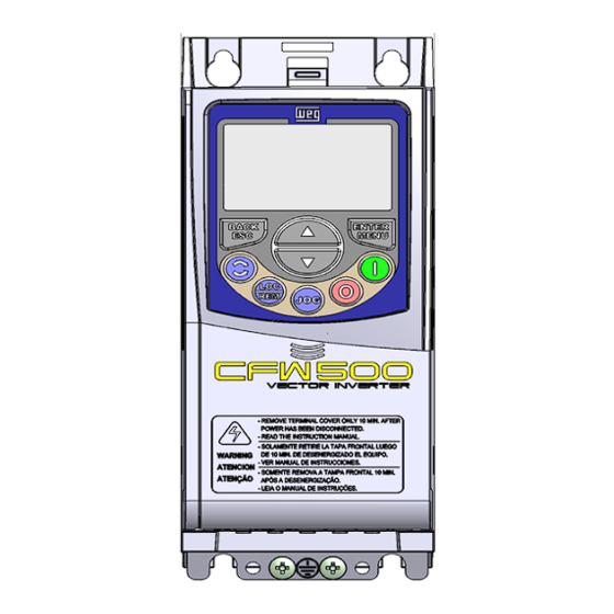
CFW500 Frequency
Inverter
1 SAFETY INSTRUCTIONS
This quick installation guide contains the basic information necessary to commission the CFW500. It has been
written to be used by qualified personnel with suitable training or technical qualification for operating this type of
equipment. The personnel shall follow all the safety instructions described in this manual defined by the local
regulations. Failure to comply with the safety instructions may result in death, serious injury, and/or equipment
damage.
2 SAFETY WARNINGS IN THIS MANUAL AND IN THE PRODUCT
DANGER!
The procedures recommended in this warning aim at protecting the user against death, serious
injuries and considerable material damages.
ATTENTION!
The procedures recommended in this warning aim at preventing material damages.
NOTE!
The information mentioned in this warning is important for the proper understanding and good
operation of the product.
High voltages present.
Components sensitive to electrostatic discharges.
Do not touch them.
The connection to the protection grounding is required (PE).
Connection of the shield to the grounding.
3 PRELIMINARY RECOMMENDATIONS
DANGER!
Always disconnect the general power supply before changing any electric component associated
to the inverter. Many components may remain loaded with high voltages and/or moving (fans), even
after the AC power supply input is disconnected or turned off. Wait for at least ten minutes in order
to guarantee the full discharge of the capacitors. Always connect the grounding point of the inverter
to the protection grounding.
NOTE!
Frequency Inverter may interfere with other electronic equipment. Follow the precautions
recommended in manual available in www.weg.net.
NOTE!
It is not the intention of this guide to present all the possibilities for the application of the CFW500,
as well as WEG cannot take any liability for the use of the CFW500 which is not based on this guide.
For further information about installation, full parameter list and recommendations, visit the website
www.weg.net.
Do not execute any applied potential test on the inverter!
If necessary, contact WEG.
ATTENTION!
Electronic boards have components sensitive to electrostatic discharges.
Do not touch directly on components or connectors. If necessary, first touch the grounding point
of the inverter, which must be connected to the protection earth (PE) or use a proper grounding
strap.
DANGER!
Crushing Hazard
In order to ensure safety in load lifting applications, electric and/or mechanical devices must be
installed outside the inverter for protection against accidental fall of load.
DANGER!
This product was not designed to be used as a safety element. Additional measures must be taken
so as to avoid material and personal damages.
The product was manufactured under strict quality control, however, if installed in systems where
its failure causes risks of material or personal damages, additional external safety devices must
ensure a safety condition in case of a product failure, preventing accidents.
ATTENTION!
The operation of this equipment requires detailed installation and operation instructions provided in
the user's manual, programming manual and communication manuals.
4 ABOUT THE CFW500
The frequency inverter CFW500 is a high-performance product which allows the speed and torque control of three-
phase induction motors. This product provides the user with the options of vector (VVW) or scalar (V/f) control, both
programmable according to the application.
In the vector mode (VVW), the operation is optimized for the motor in use, obtaining a better performance in terms
of speed regulation. The scalar mode (V/f) is recommended for simpler applications, such as the activation of most
pumps and fans. The V/f mode is used when more than a motor is activated by an inverter simultaneously
(multimotor applications).
5 NOMENCLATURA
Table 1: Nomenclature of the inverters CFW500
English
Identification of the Model
Product
Protection
and
Rated
N
of
Rated
Brake
o
Rate
Frame
Series
Current
Phases
Voltage
Ex.: CFW500
A
02P6
T
4
NB
20
See Table 2
NB = without dynamic braking
DB = with dynamic braking
CFW500
20 = IP20
N1 = cabinet Nema1 (type 1 as per UL) (protection rate
according to standard IEC IP20)
13348698
Table 2: Available options for each field of the nomenclature according to the rated current and voltage of the inverter
Available Options for the Remaining Identification
Output Rated
Rated
N° de Phases
Current
Voltage
Protection
Brake
01P6 = 1,6 A
02P6 = 2,6 A
A
NB
04P3 = 4,3 A
S = singlephase
07P0 = 7,0 A
power supply
07P3 = 7,3 A
B
DB
10P0 = 10 A
01P6 = 1,6 A
B = single-
A
02P6 = 2,6 A
NB
phase or three-
04P3 = 4,3 A
phase power
07P3 = 7,3 A
2 = 200... 240 V
supply
B
DB
10P0 = 10 A
07P0 = 7,0 A
A
NB
09P6 = 9,6 A
B
16P0 = 16 A
C
24P0 = 24 A
T = three-phase
28P0 = 28 A
power supply
DB
D
33P0 = 33 A
47P0 = 47 A
E
56P0 = 56 A
01P0 = 1,0 A
01P6 = 1,6 A
A
02P6 = 2,6 A
NB
04P3 = 4,3 A
06P1 = 6,1 A
02P6 = 2,6 A
04P3 = 4,3 A
B
06P5 = 6,5 A
4 = 380...480 V
10P0 = 10 A
14P0 = 14 A
C
T = three-phase
16P0 = 16 A
power supply
24P0 = 24 A
D
31P0 = 31 A
DB
39P0 = 39 A
E
49P0 = 49 A
01P7 = 1,7 A
03P0 = 3,0 A
04P3 = 4,3 A
C
5 = 500...600 V
07P0 = 7,0 A
10P0 = 10 A
12P0 = 12 A
6 IDENTIFICATION LABEL
Model (Smart code
of the inverter)
Serial number
Production order
Rated input data
(voltage, current
and frequency)
Figure 1: Description of the identification labels on the CFW500
7 RECEIVING AND STORAGE
The CFW500 is supplied packed in a cardboard box. On this package, there is an identification label which is the
same as the one attached to the side of the inverter.
Check if:
The identification of the CFW500 matches the model purchased.
„
Any damages occurred during transportation.
„
Report any damage immediately to the carrier.
If the CFW500 is not installed soon, store it in a clean and dry location (temperature between -25 °C and 60 °C (-77 ºF
and 140 ºF)), with a cover to prevent dust accumulation inside it.
ATTENTION!
When the inverter is stored for a long period, it becomes necessary to perform the capacitor
reforming. Refer to the procedure recommended in www.weg.net.
8 INSTALLATION AND CONNECTION
8.1 Environmental Conditions:
Avoid:
Direct exposure to sunlight, rain, high humidity or sea-air.
„
I nflammable or corrosive liquids or gases.
„
Excessive vibration.
„
Dust, metallic particles or oil mist.
„
Environmental conditions permitted for the operation of the inverter:
Temperature surrounding the inverter: from -10 ºC (14 ºF) to the nominal temperature.
„
For temperatures surrounding the inverter higher than the specifications in Table B.2 in the user's manual, it is
„
necessary to apply of 2 % of current derating for each Celsius degree, limited to an increase of 10 ºC (50 ºF).
Air relative humidity: 5 % to 95 % non-condensing.
„
Maximum altitude: up to 1000 m (3.300 ft) - nominal conditions.
„
1000 m to 4000 m (3.300 ft to 13.200 ft) - 1 % of current derating for each 100 m (328 ft) above 1000 m of altitude.
„
From 2000 m to 4000 m (6.600 ft to 13.200 ft) above sea level - maximum voltage reduction (240 V for 200...240 V models,
„
480 V for 380...480 V models and 600 V for 500...600 V models) of 1.1 % for each 100 m (330 ft) above 2000 m (6.600 ft).
Pollution degree: 2 (according to EN 50178 and UL 508C), with non-conductive pollution. Condensation must not
„
originate conduction through the accumulated residues.
8.2 Positioning and Mounting
The external dimensions and the drilling for the mounting, as well as the net weight (mass) of the inverter are
Conducted
presented in Figure 2.
Hardware
Special Software
Emission
Version
Version
Mount the inverter in the upright position on a flat and vertical surface. First, put the screws on the surface where
Level
the inverter will be installed, install the inverter and then tighten the screws observing the maximum torque for the
C2
---
---
screws indicated in Figure 2.
Blank = standard
Allow the minimum clearances indicated in Figure 3, in order to allow the cooling air circulation. Do not install heat
Sx = special
sensitive components right above the inverter.
software
Blank = standard plug-in
Viies of the mounting base
module
H00 = without plug-in
A
Blank = it does not meet the levels of
standards for conducted emission
C2 or C3 = as per category 2 (C2) or 3 (C3) of
IEC 61800-3, with internal RFI filter
Codes of the Inverters
Conducted
Hardware
Rate
Emission Level
Version
C
Blank or C2
Blank or C3
A
B
C
D
Frame
C2
mm (in) mm (in) mm (in) mm (in)
50
175
11,9
7,2
A
(1,97)
(6,89)
(0,47)
(0,28)
75
185
11,8
7,3
B
(2,95)
(7,30)
(0,46)
(0,29)
100
195
16,7
5,8
Blank
C
(3,94)
(7,70)
(0,66)
(0,23)
125
290
27,5
10,2
D
(4,92)
(11,41)
(1,08)
(0,40)
150
330
34
10.6
E
(5.9)
(13)
(1.34)
(0.4)
Dimension tolerance: ±1,0 mm (±0,039 in)
Blank or C3
(1) This value refers to the heaviest weight of the frame size.
Figure 2: Inverter dimensions for mechanical installation
Blank or
20 or N1
H00
Blank or C2
Blank or C3
Blank or C2
Blank or C3
Blank or C2
Blank or C3
(a) Surface mounting
D
Blank
Manufacturing date
WEG stock item
Rated output data
(voltage, current and
frequency)
(c) Minimum ventilation free spaces
Frame
mm (in)
A
15 (0.59)
B
35 (1.38)
C
40 (1.57)
D
40 (1.57)
E
110 (4.33)
Dimension tolerance: ±1,0 mm (±0,039 in)
(1) It is possible to mount inverters side by side without lateral free space (D = 0), however with maximum ambient temperature of 40 ºC ( 104 ºF).
Figure 3: (a) to (c) - Mechanical installation data (surface mounting and minimum ventilation free espaces)
ATTENTION!
When installing two or more inverters vertically, respect the minimum clearance A + B (as per
„
Figure 3) and provide an air deflecting plate so that the heat rising up from the bottom inverter
does not affect the top inverter.
Provide independent conduits for the physical separation of signal, control, and power cables
„
(refer to the Chapter 9 ELECTRICAL INSTALLATION).
8.3 Cabinet Mounting
For inverters installed inside cabinets or metallic boxes, provide proper exhaustion, so that the temperature remains
within the allowed range. Refer to the dissipated powers in Table 3 shows the air flow of nominal ventilation for each frame.
Cooling Method: fan with air flow upwards.
Frame
A
B
C
D (T2)*
D (T4)**
E
(*) T2 - CFW500 frame D line 200 V (200...240 V).
(**) T4 - CFW500 frame D line 400 V (380...480 V).
8.4 Surface Mounting
Figure 3 illustrates the procedure for the installation of the CFW500 on the mounting surface.
8.5 DIN-Rail Mounting
In frames A, B and C, the inverter CFW500 can also be mounted directly on 35-mm rail as per DIN EN 50.022. For
this mounting, you must first position the lock
fixing the inverter.
(*) The fastening lock of the inverter on the rail is indicated with a screwdriver in Figure 3.
9 ELECTRICAL INSTALLATION
DANGER!
The following information is merely a guide for proper installation. Comply with applicable local
„
regulations for electrical installations.
Make sure the power supply is disconnected before starting the installation.
„
The CFW500 must not be used as an emergency stop device. Provide other devices for that
„
purpose.
ATTENTION!
Front view
Side view
Integral solid state short circuit protection does not provide branch circuit protection. Branch circuit
L
P
protection must be provided in accordance with applicable local codes.
9.1 Identification of the Power Terminals and Grounding Points
The power terminals can be of different sizes and configurations, depending on the model of the inverter, according
to Table 4. The maximum torque of the power terminals and grounding points must be checked in Table 4.
Recommended
H
L
P
Weight
Mounting
Torque
Bolt
mm (in)
mm (in)
mm (in)
kg (lb)
N.m (Ibf.in)
189
75
150
0,8 (1,76)
(1)
M4
2 (17,7)
(7,44)
(2,95)
(5,91)
199
100
160
1,2 (2,65)
M4
2 (17,7)
(1)
(7,83)
(3,94)
(6,30)
210
135
165
2 (4,4)
M5
3 (26,5)
(8,27)
(5,31)
(6,50)
306,6
180
166,5
4,3 (0,16)
M6
4,5 (39,82)
(12,1)
(7,08)
(6,55)
Description of the power terminals:
350
220
191.5
L/L1, N/L2, L3 (R,S y T): AC power supply. Some models of voltage 200-240 V (see option of models in Table 10)
10 (22.05)
M6
4.5 (39.82)
(13.8)
(8.7)
(7.5)
can operate in 2 or 3 phases (single-phase/ three-phase inverters) without derating of the rated current. In this case,
the AC power supply can be connected to two of the three input terminals without distinction. For the single-phase
models only, the power voltage must be connected to L/L1 and N/L2.
U, V, W: connection for the motor.
-UD: negative pole of the voltage of the DC bus.
+UD: positive pole of the voltage of the DC bus.
BR: connection of the brake resistor.
DCR: connection to the external DC link inductor (optional). Only available for models 28 A, 33 A, 47 A and 56 A /
200-240 V and 24 A, 31 A, 39 A and 49 A / 380-480 V.
9.2 Power and Grounding Wiring, Circuit Breakers and Fuses
ATTENTION!
Use proper cable lugs for the power and grounding connection cables. Refer to Table 10 for
„
recommended wiring, circuit breakers and fuses.
Keep sensitive equipment and wiring at a minimum distance of 0.25 m from the inverter and from
„
the cables connecting the inverter to the motor.
(b) DIN rail mounting (Only Sizes A, B, C)
It is not recommended the use of mini circuit breakers (MDU), because of the actuation level
„
of the magnet
ATTENTION!
C
Residual Current Device (RCD):
When installing an RCD to guard against electrical shock, only devices with a trip current of
„
300 mA should be used on the supply side of the inverter.
Depending on the installation (motor cable length, cable type, multimotor configuration, etc.),
„
the RCD protection may be activated. Contact the RCD manufacturer for selecting the most
appropriate device to be used with inverters.
NOTE!
The wire gauges listed in Table 10 sare orientative values. Installation conditions and the maximum
„
permitted voltage drop must be considered for the proper wiring sizing.
In order to meet UL requirements, use ultra fast (for frame sizes A, B and C), and use fuse type J
„
or circuit breaker (for frame sizes D and E) fuses at the inverter supply with a current not higher
than the values presented in Table 10.
9.3 Power Connections
A
B
C
D
mm (in)
mm (in)
mm (in)
40 (1.57)
30 (1.18)
10 (0.39)
(1)
50 (1.97)
40 (1.57)
15 (0.59)
(1)
50 (1.97)
50 (1.97)
30 (1.18)
50 (1.97)
50 (1.97)
40 (1.57)
130 (5.11)
50 (1.96)
40 (1.57)
PE
Input
PE
power
supply
R
S
T
Disconnecting
Fuses
switch
(*) The power terminals -Ud, BR and +Ud are not available in models of frame A.
(a) Frames A, B and C
9.3.1 Input Connections
DANGER!
Provide a disconnect device for the inverter power supply. This device must cut off the power supply
whenever necessary (during maintenance for instance).
Table 3: Air flow of the fan
CFM
I/s
m
/min
3
ATTENTION!
20
9.4
0.56
30
14.1
0.85
The power supply that feeds the inverter must have a grounded neutral. In case of IT networks,
30
14.1
0.85
follow the instructions described in the user's manual.
100
47.2
2.83
80
37.8
2.27
NOTE!
180
84.5
5.09
The input power supply voltage must be compatible with the inverter rated voltage.
„
Power factor correction capacitors are not needed at the inverter input (L/L1, N/L2, L3 or R, S,
„
T) and must not be installed at the output (U, V, W).
Power supply capacity
Suitable for use in circuits capable of delivering not more than 30.000 Arms symmetrical (200 V, 480 V or 600 V),
„
when protected by fuses as specified in Table 10.
9.3.2 Inductor of the DC Link/ Reactance of the Power Supply
(*)
down and then place the inverter on the rail, position the lock
(*)
up,
In order to prevent damages to the inverter and assure the expected useful life, you must have a minimum
„
impedance that provide a voltage drop of the input power supply of 1 %. If the impedance of the input power
supply (due to the transformers and cabling) is below the values listed in this table, we recommend the use of
reactance in the input power supply.
Table 4: Power terminals, grounding points and recommended tightening torque
Recommended Torque
Frame
Power Supply
Grounding Points
Power Terminals
N.m
Lbf.in
N.m
Lbf.in
200...240 V
0,5
4,34
0,5
4,34
A
380...480 V
0,5
4,34
0,5
4,34
200...240 V
0,5
4,34
0,5
4,34
B
380...480 V
0,5
4,34
0,5
4,34
200...240 V
0,5
4,34
1,7
15,00
C
380...480 V
0,5
4,34
1,8
15,93
500...600V
0,5
4,34
1,0
8,68
200...240 V
0,5
4,34
2,4
21,24
D
380...480 V
0,5
4,34
1,76
15,57
200...240 V
0.5
4.34
3.05
27
E
380...480 V
0.5
4.34
3.05
27
.
R S
T
-Ud
BR
+Ud
U
V
W
R
S
T
-UD
BR
+UD
DCR
U
V
W
PE
PE
PE
(*)
Input
PE
U V W
U V
PE
U V
U V W
W
PE
W
PE
power
Shield
supply
Shield
R
S
T
Disconnecting
Fuses
switch
(b) Frames D and E
Figure 4: (a) and (b) - Power and grounding connections
Advertisement
Table of Contents

Subscribe to Our Youtube Channel
Related Manuals for Weq CFW500


Summary of Contents for Weq CFW500
- Page 1 If the CFW500 is not installed soon, store it in a clean and dry location (temperature between -25 °C and 60 °C (-77 ºF (*) The power terminals -Ud, BR and +Ud are not available in models of frame A.
-
Page 2: Optional Kits And Accessories
(2) In order to comply with UL508C standard, use UL ultra fast fuses, for frames A, B, and C. (3) In order to comply with UL508C standard, use fuses UL type J for frame D. (4) The models of the CFW500 frame E are under certification process. Therefore, they still do not have UL certification.
Need help?
Do you have a question about the CFW500 and is the answer not in the manual?
Questions and answers