Table of Contents
Advertisement
Advertisement
Table of Contents

Subscribe to Our Youtube Channel
Related Manuals for Ariens Sno-Thro Deluxe Track 24


Summary of Contents for Ariens Sno-Thro Deluxe Track 24
- Page 1 Sno-Thro ® Owner/Operator Manual Models 921305 – Deluxe 24 921306 – Deluxe 27 921307 – Deluxe 30 921311 – Deluxe Track 24 921312 – Deluxe Track 27 ENGLISH FRANÇAIS DEUTSCH ITALIANO SUOMI ESPAÑOL NORSK SVENSKA РУССКИЙ ЯЗЫК POLSKI TÜRKÇE 03882715B 12/09 ČESKY Printed in USA...
- Page 2 PRODUCENTA – ES PROHLÁŠENÍ O SHODĚ, VYDANÉ VÝROBCEM (920) 756-2407 We the undersigned, ARIENS COMPANY, certify that: Nous, soussignés ARIENS COMPANY, certifions que : Der Unterzeichnete, ARIENS COMPANY, bescheinigt, dass: La sottoscritta società ARIENS COMPANY certifica che: Nosotros, los abajo firmantes, ARIENS COMPANY, certificamos que: Undertegnede, ARIENS COMPANY, bekrefter at: Undertecknad, ARIENS COMPANY, intygar att: Allekirjoittanut, ARIENS COMPANY, vakuuttaa, että: My, niŸej podpisani, ARIENS COMPANY,...
- Page 3 Technical File) / Directeur Conformité et Garantie des Datum Dato Data produits (Gardien du fichier technique) / Direktor Fecha Dato Produktkonformität und Gewährleistung Datum Päiväys Ariens Company (Aufbewahrungsstelle der technischen Dokumentation) Data Data Datum Brillion, WI 54110-0157 USA / Directeur Productconformiteit en -garantie (Beheerder Signature Signature Unterschrift technische documentatie) / Direktør for varekonformitet...
-
Page 4: Table Of Contents
If used Dealer. Visit your dealer or improperly, this unit could be dangerous and www.ariens.eu for a list of cause personal injury or property damage. languages available for your The contents will provide you with safety equipment. - Page 5 6. Fill out a Product Registration Card and UNAUTHORIZED REPLACEMENT return the card to the Ariens Company or PARTS go to www.ariens.com. Use only Ariens replacement parts. The replacement of any part on this vehicle with...
-
Page 6: Safety
SAFETY PRACTICES AND LAWS WARNING: To avoid injury to Practice usual and customary safe working hands and feet, always disengage precautions, for the benefit of yourself and clutches, shut off engine, and wait others. Understand and follow all safety for all movement to stop before messages. - Page 7 3. DANGER! Keep people away from unit while operating. Keep children out of work area and under ROTATING PARTS. watchful care of a responsible Keep clear of auger while adult. engine is running. OL4370 • Read Operator’s Manual. • Allow operation only by OS2080 properly trained adult, Never direct discharge towards...
- Page 8 DO NOT operate near drop-offs, ditches, or ALWAYS disengage attachment, stop unit embankments. Unit can suddenly turn over if and engine, remove key and allow moving a wheel is over the edge of a cliff or ditch, or if parts to stop before leaving operator’s an edge caves in.
- Page 9 Check clutch and brake operation frequently. Keep the nozzle in contact with the rim of the Adjust and service as required. All motion of fuel tank or container opening at all times until drive wheels and auger/impeller must stop fueling is complete. Do not use a nozzle lock- quickly when control levers are released.
-
Page 10: Assembly
ASSEMBLY Unfold Handlebar (Figure 4) WARNING: AVOID INJURY. Read 1. Remove the lower and loosen the upper and understand the entire Safety hardware on the handlebar assembly. section before proceeding. 2. Loosen the hardware on the shift rod. 3. Put the speed selector lever in the second reverse position. - Page 11 Remote Deflector Control (921306, 307, 311, 312) (Figure 6) Connect the cable end to the cable anchor on the discharge deflector before clipping the cable to the cable bracket on the discharge chute. 1. Route deflector remote cable along the left side of the chute pedestal.
- Page 12 Check Function of Dual Handle Check Track Tension Interlock (921305, 306, 307) Without the engine running, press down Check tracking of unit with the differential (engage) both clutch levers. Release locked,and tension of tracks (see Track attachment clutch lever. Attachment clutch Tension Adjustment on page 31).
-
Page 13: Controls And Features
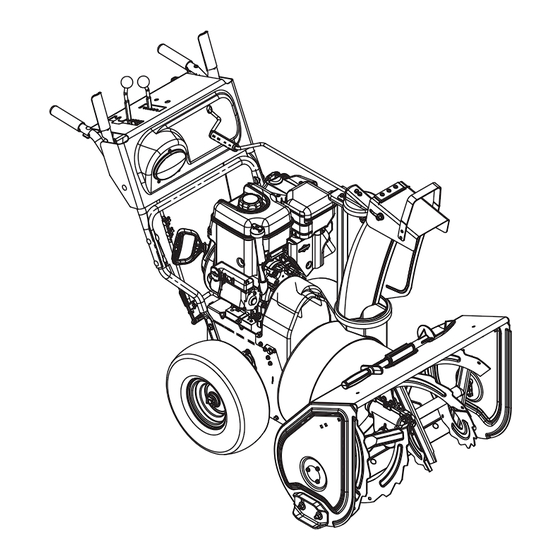
CONTROLS AND FEATURES Figure 7 1. Oil Drain 15. Height Adjuster Trigger (311, 312) 2. Fuel Shut-Off Valve 16. Runner 3. Primer Bulb 17. Clean-Out Tool 4. Recoil Starter Handle 18. Remote Discharge Chute Deflector 5. Throttle (Engine Stop) 19. Manual Discharge Chute Deflector 6. -
Page 14: Operation
OPERATION Attachment Clutch - Right Hand WARNING: AVOID INJURY. Read Lever and understand the entire Safety section before proceeding. Squeeze Attachment Clutch Lever against handlebar (1) to WARNING: To avoid injury to hands engage attachment. and feet, always disengage Release both clutch clutches, shut off engine, and wait levers (2) to disengage for all movement to stop before... - Page 15 Speed Selector Snow Clean-Out Tool Position the Speed Selector in the (Figure 8) appropriate speed notch to control forward and reverse travel. WARNING: Hand contact with the Forward: rotating impeller is the most common cause of injury associated (6) Fastest with snow throwers.
- Page 16 Manual Discharge Deflector (921305) Axle Lock Pin (921305) ALWAYS position discharge chute deflector (Figure 11) at a safe angle before starting engine. DO Use the axle lock pin to lock or unlock the NOT throw snow any higher than necessary. right or left wheel.
- Page 17 Track Angle FILLING FUEL TANK (921311, 312) WARNING: AVOID INJURY. Read (Figure 12) and understand the entire Safety The track angle can be adjusted to position section before proceeding. the auger housing for level clearing, deep cutting or transport. Fuel Shut-Off Valve Squeeze the handlebar trigger and press IMPORTANT: The fuel shut-off valve MUST down on the handlebars to move the auger...
- Page 18 GASOLINE 2. Check Function of Clutches If clutches do not engage or disengage IMPORTANT: ALWAYS use gasoline that properly, adjust or repair before operation. meets the following guidelines: See Attachment Clutch/Brake Adjustment on • Clean, fresh gasoline. page 25 and Traction Drive Clutch •...
- Page 19 Owner/Operator Manual and the IMPORTANT: Use an extension cord that is Engine Manual first. capable of handling current requirements. See your Ariens dealer for recommended IMPORTANT: Allow unit and engine to adjust extension cord. to the outdoor temperature before clearing snow.
-
Page 20: Maintenance
ALWAYS direct snow away from area to be cleared and with direction of the wind. MAINTENANCE Ariens Dealers will provide any service or IMPORTANT: Ensure unit is secure and will not tip over. Strap and clamp onto bench if adjustments which may be required to keep needed. - Page 21 MAINTENANCE SCHEDULE CHECK CLUTCH OPERATION The chart below shows the recommended Auger / impeller must stop within 5 seconds maintenance schedule that should be when attachment clutch/impeller brake lever performed on a regular basis. More frequent is released. service may be required. Wheels must stop quickly when traction drive clutch lever is released.
- Page 22 Check oil level each season or NOTE: Apply Ariens Hi-Temp Grease or every 25 hours of operation. equivalent to the lubrication fittings. See To ensure adequate lubricant level: SERVICE PARTS on page 32.
-
Page 23: Service And Adjustments
SERVICE AND ADJUSTMENTS SHEAR BOLTS WARNING: AVOID INJURY. Read IMPORTANT: Use only Ariens shear bolts for and understand the entire Safety replacement. Use of any other type of shear section before proceeding. bolt may result in severe damage to unit. See SERVICE PARTS on page 32. - Page 24 4. To adjust deflector higher: DISCHARGE CHUTE Slide cable up. Tighten top nut. If discharge chute does not stay in position 5. Check travel and repeat adjustment as while operating, tighten nut on carriage bolt at necessary. pivot point to increase tension on spring (Figure 21).
- Page 25 e. Shift speed selector into first reverse speed. f. Engage the traction clutch. Unit should move backward. g. Shut off unit. 8. Adjust pivot pin on the shift rod as necessary so unit travels forward when speed selector is in first forward position and travels backward when speed selector is in first reverse position.
- Page 26 12.7 –- 14.3 mm OS7189 Figure 26 OS7184 OS7183 Roller should be 12.7 – 22.2 mm from the frame when the attachment clutch is 2. Adjust cable length (Figure 27). engaged. a. Loosen jam nut on cable. b. To increase spring extension Figure 25 adjust barrel down the cable and tighten jam nut.
- Page 27 Check Attachment Brake Check Belt Finger Clearance (Figure 28) 1. With clutch lever engaged, the belt finger located opposite the belt idler 1. With the clutch lever disengaged, brake must be less than 3 mm from belts, but pad must contact attachment belts. With not touching the belts (Figure 29).
- Page 28 177.8 – 190.5 mm Figure 30 OS7206 4. To adjust traction clutch (Figure 31): a. With the traction drive clutch lever disengaged, loosen the jam nut on the cable adjuster. b. Turn the adjuster body up the cable to decrease the distance between the clutch lever and handlebar.
- Page 29 5. Check adjustment. See Attachment Clutch/Brake Adjustment on page 25. WARNING: AUGER / IMPELLER MUST STOP within 5 seconds when attachment clutch lever is released or unit damage or serious injury may result. 6. Reconnect chute crank and secure with spring clip.
- Page 30 FRICTION DISC REPLACEMENT 1. Shut off engine, remove key, disconnect spark plug wire and allow unit to cool completely. 2. Place unit into service position on a level surface. 3. Remove both wheels. 4. Remove bottom cover by removing six hex bolts.
- Page 31 2. Check that unit tracks straight with no pulling to either side. Track Adjusters Figure 38 OS7228 HEIGHT ADJUSTER CABLE ADJUSTMENT (921311, 312) 1. Make sure that height adjustment lock OS7142 finger is fully engaged (Figure 39). 1. Hex Shaft 4.
-
Page 32: Storage
ACCESSORIES Keep all nuts, bolts and screws properly tightened and know unit is in safe working See your authorized Ariens dealer to add condition. the additional accessories available to your Sno-Thro. Store unit in a cool, dry protected area. -
Page 33: Troubleshooting
TROUBLESHOOTING PROBLEM PROBABLE CAUSE CORRECTION Engine will not 1. Fuel tank is empty. 1. Fill fuel tank. crank/start. 2. Fuel shut-off valve closed. 2. Open fuel shut-off valve. 3. Build up of dirt and residue 3. Clean area around around governor/carburetor. -
Page 34: Specifications
SPECIFICATIONS Model Number 921305 921306 921307 Description Deluxe 24 Deluxe 27 Deluxe 30 Engine Engine Model Briggs & Stratton Briggs & Stratton Briggs & Stratton 1150 Snow Series 1450 Snow Series 1650 Snow Series Gross Torque* - N-m 15.59 19.66 22.37 *Engine output stated in gross torque per SAE J1940 as rated by engine manufacturer Displacement - cc... - Page 35 SPECIFICATIONS Model Number 921311 921312 Description Deluxe Track 24 Deluxe Track 27 Engine Engine Briggs & Stratton 1150 Briggs & Stratton 1450 Snow Series Snow Series Gross Torque* - N-m 15.59 19.66 *Engine output stated in gross torque per SAE J1940 as rated by engine manufacturer Displacement - cc High Idle - RPM (min) 3600 ±...
- Page 36 Ariens Company 655 West Ryan Street Brillion, WI 54110-1072 920-756-2141 Fax 920-756-2407 www.ariens.eu Protective Floor Mat Protects floor from rust, dirt and snow melt.
Need help?
Do you have a question about the Sno-Thro Deluxe Track 24 and is the answer not in the manual?
Questions and answers