Advertisement
Operator's Manual
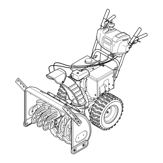
Two-Stage Snow Thrower
Model No.
C459-52538 (30")
CAUTION: Before using this
product, read this manual
and follow all safety rules
and operating instructions.
FOR CUSTOMER ASSISTANCE CALL 1-800-668-1238
PRINTED IN U.S.A.
®
• SAFETY
• ASSEMBLY
• OPERATION
• MAINTENANCE
• PARTS LIST
769-10005B
6.10.15
Advertisement
Table of Contents

Related Manuals for Craftsman C459-52538


Summary of Contents for Craftsman C459-52538
- Page 1 Operator’s Manual ® Two-Stage Snow Thrower Model No. C459-52538 (30”) • SAFETY • ASSEMBLY • OPERATION • MAINTENANCE • PARTS LIST CAUTION: Before using this product, read this manual and follow all safety rules and operating instructions. FOR CUSTOMER ASSISTANCE CALL 1-800-668-1238 769-10005B PRINTED IN U.S.A.
-
Page 2: Table Of Contents
To The Owner Thank You Thank you for purchasing your new equipment. It was carefully The manufacturer reserves the right to change product engineered to provide excellent performance when properly specifications, designs and equipment without notice and operated and maintained. without incurring obligation. -
Page 3: Safe Operation Practices
Important Safe Operation Practices WARNING! This symbol points out important safety instructions which, if not followed, could endanger the personal safety and/or property of yourself and others. Read and follow all instructions in this manual before attempting to operate this machine. Failure to comply with these instructions may result in personal injury. - Page 4 Safe Handling of Gasoline Never run an engine indoors or in a poorly ventilated area. Engine exhaust contains carbon monoxide, an odorless To avoid personal injury or property damage use extreme care and deadly gas. in handling gasoline. Gasoline is extremely flammable and the Do not operate machine while under the influence of vapors are explosive.
- Page 5 Clearing a Clogged Discharge Chute According to the Consumer Products Safety Commission (CPSC) and the U.S. Environmental Protection Agency (EPA), Hand contact with the rotating impeller inside the discharge this product has an Average Useful Life of seven (7) years, chute is the most common cause of injury associated with snow or 60 hours of operation.
- Page 6 Safety Symbols This page depicts and describes safety symbols that may appear on this product. Read, understand, and follow all instructions on the machine before attempting to assemble and operate. Symbol Description READ THE OPERATOR’S MANUAL(S) Read, understand, and follow all instructions in the manual(s) before attempting to assemble and operate WARNING—...
-
Page 7: Assembly & Set-Up
Assembly & Set-Up IMPORTANT: The snow thrower is shipped with oil and WITHOUT NOTE: Make certain the cables are seated properly in the GASOLINE. After assembly, refer to separate engine manual for roller guides. See Figure 3-2. proper fuel and engine oil recommendations. NOTE: Remove all loose parts and any packing material before assembling. - Page 8 Chute Assembly (If Equipped w/ Electric Chute Control) Place chute onto chute base and ensure chute control rod is positioned under the handle panel. Secure chute control Remove cotter pin, wing nut and hex screw from chute assembly to chute support bracket with clevis pin and control assembly.
- Page 9 NOTE: For smoothest operation, the cables should all be to the left of the chute directional control rod. Figure 3-7 Push the chute control rod toward the control panel until the hole in the rod lines up with the middle hole in the Figure 3-9 chute control input and insert the cotter pin.
- Page 10 Chute Clean-Out Tool The chute clean-out tool and cord are fastened to the top of the auger housing with a mounting clip and a cable tie at the factory. Cut the cable tie before operating the snow thrower. See Figure 3-11.
- Page 11 Confirm that the auger has completely stopped rotating and shows NO signs of motion. If the auger shows ANY signs of rotating, immediately return to the operator’s position and shut off the engine. Wait for ALL moving parts to stop before re-adjusting the auger control. To readjust the control cable, loosen the upper hex screw on the auger cable bracket.
-
Page 12: Controls
Controls and Features Drive Control Electric Chute Control Shift Lever Auger Control Headlight Wheel Steering Control Manual Chute Control Chute Assembly Clean-Out Drift Cutter Tool Augers Skid Shoe Figure 4-1 Skid Shoes Snow thrower controls and features are described below and illustrated in Fig. - Page 13 Drift Cutters (if so equipped) Steering Trigger Controls The drift cutters are designed for use in deep snow. Their use is optional for normal snow conditions. Maneuver the snow thrower so that the cutters penetrate a high standing snow drift to assist snow falling into the augers for throwing.
- Page 14 Manual Chute Directional Control Grasp the indented portion of the chute control rod and manually rotate the chute assembly to the right or to the Proceed as follows to utilize the manual chute directional control: left. See Figure 4-3. Remove the cotter pin from either of the holes furthest from the chute assembly on the chute rotation assembly.
-
Page 15: Operation
Operation Starting and Stopping the Engine Replacing Shear Pins Refer to the Engine Operator’s Manual packed with your snow The augers are secured to the spiral shaft with shear pins and thrower for instructions on starting and stopping the engine. bow-tie cotter pins. -
Page 16: Maintenance & Adjustment
Maintenance & Adjustments Maintenance Lubrication Engine Gear Shaft Refer to the Engine Operator’s Manual packed with your snow The gear (hex) shaft should be lubricated at least once a season thrower. or after every twenty-five (25) hours of operation. Allow the engine to run until it is out of fuel. Tire Pressure Carefully pivot the snow thrower up and forward so that it Refer to “Assembly and Set-Up”... - Page 17 Chute Assembly Refer to the Assembly & Set-up section for instructions on adjusting the chute assembly. Skid Shoes Refer to the Assembly & Set-up section for instructions on adjusting the skid shoes. Drive Control When the drive control is released and in the disengaged “up” position, the cable should have very little slack.
- Page 18 Chute Directional Control Off-Season Storage To adjust the chute control rod, proceed as follows: If the snow thrower will not be used for 30 days or longer, follow the storage instructions below. Remove the cotter pin from either of the holes closest to the chute assembly on the chute rotation assembly.
-
Page 19: Service
Service Belt Replacement Roll the auger belt off the engine pulley. See Fig. 7-3. Auger Belt To remove and replace your snow thrower’s auger belt, proceed as follows: Allow the engine to run until it is out of fuel. Do not attempt to pour fuel from the engine. - Page 20 Drive Belt Remove the belt as follows. See Fig. 7-5. Loosen and remove the shoulder bolt which acts as NOTE: Special tools are required and several components must a belt keeper. be removed in order to replace the snow thrower’s drive belt. See an authorized Service Dealer to have the drive belt replaced or Unhook the brake bracket spring from the frame.
-
Page 21: Troubleshooting
Troubleshooting Problem Cause Remedy Engine fails to start 1. Choke not in CHOKE position. 1. Move choke to CHOKE position. 2. Spark plug wire disconnected. 2. Connect wire to spark plug. 3. Fuel tank empty or stale fuel. 3. Fill tank with clean, fresh gasoline. 4. -
Page 22: Replacement Parts
Replacement Parts Component Part Number and Description 929-0071A Extension Cord, 110V 954-04050A Auger Drive Belt (24”) 954-04260 Wheel Drive Belt (24”) 954-04195A Auger Drive Belt (26”, 28” & 30”) 954-04201A Wheel Drive Belt (26”, 28” & 30”) 684-04153C Friction Wheel Assembly 935-04054 Friction Wheel Rubber 925-1629... -
Page 23: Warranty
Warranty General: Craftsman products are warranted to be free from defects in materials or workmanship for a specific time period as set-out below (the “Warranty Period”). Warranties extend to the original purchaser of a Craftsman product only. Purchases made through an online auction or through any website other than www.sears.ca are excluded. -
Page 24: Parts & Service Agreement
Sears Parts & Protection Agreement ervice WE’RE THERE FOR YOU LONG AFTER THE SALE To purchase replacement parts and product accessories, call 1.800.4.MY.HOME (1.800.469.4663), visit Sears.ca/parts, or visit your nearest Sears Parts and Repair store. Delivery to your home is available. 1-800-361-6665 To purchase or inquire about a Sears Protection Agreement, call: To schedule a service call for a product covered by a Protection Agreement and out of... -
Page 25: Protection Agreement
Protection Agreements Congratulations on making a smart purchase. Your new Craftsman® product is designed and manufactured for years of dependable operation. But like all products, it may need to be repaired. That’s when having a Protection Agreement can save you money, time and aggravation. - Page 26 Notes...
Need help?
Do you have a question about the C459-52538 and is the answer not in the manual?
Questions and answers