Advertisement
Operator's Manual
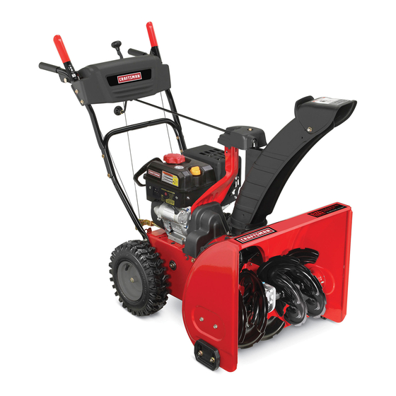
TWO STAGE SNOW THROWERS
Model Nos. C459-52413 (24")
C459-52415 (28")
CAUTION: Before using this
product, read this manual
and follow all safety rules
and operating instructions.
FOR CUSTOMER ASSISTANCE CALL 1-800-668-1238
PRINTED IN U.S.A.
®
• SAFETY
• ASSEMBLY
• OPERATION
• MAINTENANCE
• PARTS LIST
769-09968
06/11/14
Advertisement
Table of Contents

Related Manuals for Craftsman C459-52413


Summary of Contents for Craftsman C459-52413
- Page 1 Operator’s Manual ® TWO STAGE SNOW THROWERS Model Nos. C459-52413 (24”) C459-52415 (28”) • SAFETY • ASSEMBLY • OPERATION • MAINTENANCE • PARTS LIST CAUTION: Before using this product, read this manual and follow all safety rules and operating instructions.
-
Page 2: Table Of Contents
To The Owner Thank You Thank you for purchasing your new equipment. It was carefully The manufacturer reserves the right to change product engineered to provide excellent performance when properly specifications, designs and equipment without notice and operated and maintained. without incurring obligation. -
Page 3: Safe Operation Practices
Important Safe Operation Practices WARNING! This symbol points out important safety instructions which, if not followed, could endanger the personal safety and/or property of yourself and others. Read and follow all instructions in this manual before attempting to operate this machine. Failure to comply with these instructions may result in personal injury. - Page 4 Safe Handling of Gasoline Never run an engine indoors or in a poorly ventilated area. Engine exhaust contains carbon monoxide, an odorless To avoid personal injury or property damage use extreme care and deadly gas. in handling gasoline. Gasoline is extremely flammable and the Do not operate machine while under the influence of vapors are explosive.
- Page 5 Clearing a Clogged Discharge Chute According to the Consumer Products Safety Commission (CPSC) and the U.S. Environmental Protection Agency (EPA), Hand contact with the rotating impeller inside the discharge this product has an Average Useful Life of seven (7) years, chute is the most common cause of injury associated with snow or 60 hours of operation.
- Page 6 Safety Symbols This page depicts and describes safety symbols that may appear on this product. Read, understand, and follow all instructions on the machine before attempting to assemble and operate. Symbol Description READ THE OPERATOR’S MANUAL(S) Read, understand, and follow all instructions in the manual(s) before attempting to assemble and operate.
-
Page 7: Assembly & Set-Up
Assembly & Set-Up NOTE: Remove all loose parts and any packing material before assembling. NOTE: References to right or left side of the snow thrower are determined from behind the unit in the operating position. NOTE: This Operator’s Manual covers several models, handle panels, lights and chute cranks are some features that may vary by model. - Page 8 Squeeze the trigger on the joystick and rotate the chute by hand to face forward. The holes in the chute rotation assembly will be facing up. See Fig. 3-6. NOTE: The chute will not rotate without squeezing the trigger on the joystick. Chute Rotation Top View Assembly...
- Page 9 Insert the hex end of the rod (hole pointing upward) into Finish securing chute rotation assembly to chute support the pinion gear. See Fig. 3-8. bracket with wing nut, clevis pin and cotter pin removed earlier. See Fig. 3-3. NOTE: The chute control rod will fit snuggly into the pinion gear.
- Page 10 Clean-Out Tool • Reposition drift cutters so they face forward as shown in Fig. 3-13. Secure with hardware previously removed, The clean-out tool is mounted to the rear of the auger housing wingnuts should be fastened on the outside of the housing and is designed to clear a clogged chute.
- Page 11 • For close snow removal on a smooth surface, raise skid shoes higher on the auger housing. • Use a middle or lower position when the area to be cleared is uneven, such as a gravel driveway. NOTE: If you choose to operate the snow thrower on a gravel surface, keep the skid shoes in position for maximum clearance between the ground and the shave plate.
-
Page 12: Controls
Controls and Features Shift Lever Drive Control Four-Way Chute Control™ (Joystick) Auger Control Headlight Heated Grips Gas Cap Wheel Steering Control Chute Assembly Drift Cutters Clean Out Tool Augers Skid Shoe Fig. 4-1 Skid Shoes Snow thrower controls and features are described below and illustrated in Fig. - Page 13 Drift Cutters (if so equipped) Steering Trigger Controls (if so equipped) The drift cutters are designed for use in deep snow. Their use is optional for normal snow conditions. Maneuver the snow thrower so that the cutters penetrate a high standing snow drift to assist snow falling into the augers for throwing.
- Page 14 Four-Way Chute Control™ The chute directional control is located on the left side of the dash panel. • To change the direction in which snow is thrown, squeeze the button on the joy-stick and pivot the joy-stick to the right or to the left. •...
-
Page 15: Operation
Operation Starting and Stopping the Engine Replacing Shear Pins Refer to the Engine Operator’s Manual packed with your snow The augers are secured to the spiral shaft with two shear thrower for instructions on starting and stopping the engine. pins and cotter pins. If the auger should strike a foreign object or ice jam, the snow thrower is designed so that the To Engage Drive pins may shear. -
Page 16: Maintenance & Adjustment
Maintenance & Adjustments Maintenance Lubrication Engine Gear Shaft Refer to the Engine Operator’s Manual packed with your snow The gear (hex) shaft should be lubricated at least once a season thrower. or after every twenty-five (25) hours of operation. Allow the engine to run until it is out of fuel. Tire Pressure Carefully pivot the snow thrower up and forward so that it Refer to “Assembly and Set-Up”... - Page 17 Chute Assembly Refer to the Assembly & Set-up section for instructions on adjusting the chute assembly. Skid Shoes Refer to the Assembly & Set-up section for instructions on adjusting the skid shoes. Drive Control When the drive control is released and in the disengaged “up” position, the cable should have very little slack.
- Page 18 Chute Control Rod Off-Season Storage If the snow thrower will not be used for 30 days or longer, follow To adjust the chute control rod, proceed as follows: the storage instructions below. Remove the cotter pin from the hole closest to the chute Lubricate the machine as instructed earlier in this section.
-
Page 19: Service
Service Belt Replacement Roll the auger belt off the engine pulley. See Fig. 7-3. Auger Belt To remove and replace your snow thrower’s auger belt, proceed as follows: Allow the engine to run until it is out of fuel. Do not attempt to pour fuel from the engine. - Page 20 Drive Belt Remove the belt as follows. See Fig. 7-5. Loosen and remove the shoulder bolt which acts as To remove and replace your snow thrower’s drive belt, proceed a belt keeper. as follows: Unhook the brake bracket spring from the frame. To prevent spillage, remove all fuel from tank by running engine until it stops.
- Page 21 Back out the stop bolt to increase the clearance between the friction wheel disc and friction wheel. See Fig. 7-8. Slip the drive belt off the pulley and between friction wheel and friction wheel disc. See Fig. 7-8. Remove and replace belt in the reverse order, and return stop bolt to original position.
- Page 22 NOTE: Be careful not to damage the threads on the shaft. If you’re disassembling the friction wheel and replacing only the rubber ring, proceed as follows: Carefully position the hex shaft downward and to the left before carefully sliding the friction wheel assembly off the Remove the four screws which secure the friction wheel’s shaft.
-
Page 23: Troubleshooting
Troubleshooting Problem Cause Remedy Engine fails to start 1. Choke not in CHOKE position. 1. Move choke to CHOKE position. 2. Spark plug wire disconnected. 2. Connect wire to spark plug. 3. Fuel tank empty or stale fuel. 3. Fill tank with clean, fresh gasoline. 4. -
Page 24: Replacement Parts
Replacement Parts Component Part Number and Description 929-0071A Extension Cord, 110V 954-04050A Auger Drive Belt (24”) 954-04260 Wheel Drive Belt (24”) 954-04195A Auger Drive Belt (26”, 28” & 30”) 954-04201A Wheel Drive Belt (26”, 28” & 30”) 684-04153C Friction Wheel Assembly 935-04054 Friction Wheel Rubber 925-1629... -
Page 25: Emissions Control Warranty Statement
TWO YEAR LIMITED WARRANTY The limited warranty set forth below is given by MTD Products Limited (“MTD”) with respect to new merchandise purchased and used in Canada and/or its territories and possessions. MTD warrants this product (excluding its normal wear parts as described below) against defects in material and workmanship for a period of two (2) years commencing on the date of original purchase and will, at its option, repair or replace, free of charge, any part found to be defective in materials or workmanship. -
Page 26: Warranty
FEDERAL and/or CALIFORNIA EMISSION CONTROL WARRANTY STATEMENT YOUR WARRANTY RIGHTS AND OBLIGATIONS MTD Consumer Group Inc, the United States Environmental Protection Agency (EPA), and for those products certified for sale in the state of California, the California Air Resources Board (CARB) are pleased to explain the emission control system (ECS) warranty on your 2013- 2014 small off-road spark-ignited engine and equipment (outdoor equipment). - Page 27 Any replacement part may be used in the performance of any warranty maintenance or repairs and must be provided without charge to the owner. Such use will not reduce the warranty obligations of MTD Consumer Group Inc. Add-on or modified parts that are not exempted by the Air Resources Board may not be used. The use of any non-exempted add-on or modified parts by the ultimate purchaser will be grounds for disallowing a warranty claim.
- Page 28 Notes...
Need help?
Do you have a question about the C459-52413 and is the answer not in the manual?
Questions and answers