
Related Manuals for YOSUDA X-1-01A


Summary of Contents for YOSUDA X-1-01A
- Page 1 YOSUDA X-BIKE ASSEMBLY MANUAL X-1-01A IMPORTANT! Please read this manual before assembling and using. Retain owner’s manual for using instructions. Your satisfaction is very important to us, PLEASE CONTACT US: yosudasports@gmail.com...
-
Page 2: Table Of Contents
CATALOGUE CUSTOMER SERVICE ..............1 ASSEMBLING VIDEO ..............1 IMPORTANT SAFETY INFORMATION ........... 2 PRODUCT PROFILE ............... 5 ASSEMBLY INSTRUCTIONS ............7 Step 1 ....................7 Step 2 ....................8 Step 3 ....................9 Step 4 ....................10 Step 5 ....................11 Step 6 ....................12 Step 7 ....................13 Step 8 ....................14 Step 9 ....................15 ADJUST THE RESISTANCE ............ -
Page 3: Customer Service
CUSTOMER SERVICE Feel free to contact our customer service if any needs: yosudasports@gmail.com Contact us via Amazon: Login your Amazon account > choose "Your orders" > find the order ID > click "Contact seller" ASSEMBLING VIDEO Download the Amazon Shopping APP ... -
Page 4: Important Safety Information
IMPORTANT SAFETY INFORMATION Please note the following safety warnings and precautions before assembling and using the equipment. It is your responsibility to ensure that all users of the equipment are informed of all warnings and precautions. 1. Wear suitable sports clothes and sports shoes while using the equipment, especially the sports shoes must fit. - Page 5 caused by diabetes, etc. 10) Those with skin trauma. 11) Those who have a high fever (38 degrees or more) due to illness, etc. 12) Abnormal or curved back bones. 13) Women who are pregnant or may become pregnant or are menstruating. 14) Those who feel abnormal in their body and need to rest.
- Page 6 17. DO NOT use it after eating, when you are tired, when you have just exercised or when your physical state is abnormal. ---- May cause damage to health. 18. DO NOT use it while eating or doing other activities. 19.
-
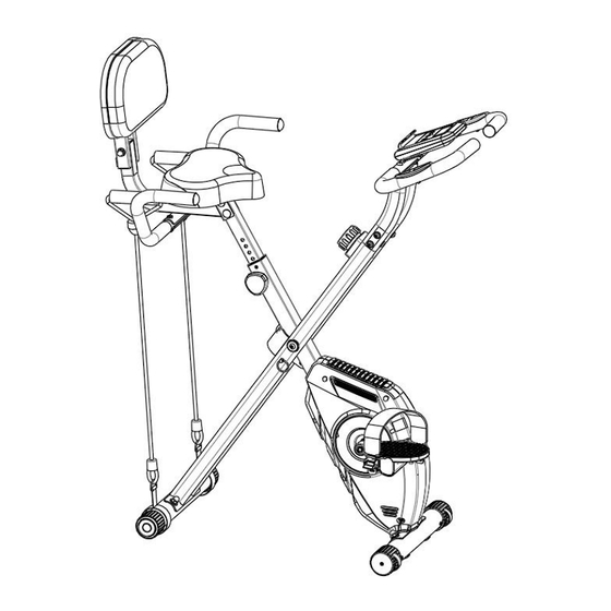
Page 7: Product Profile
PRODUCT PROFILE... - Page 8 Main configure list Name Name Name Main Frame Support Tube Seat Post Front Stabilizer Handlebar with Rear Stabilizer Hand Pulse Grips Backrest Support piece Seat Handlebar Handlebar Support Seat Cushion piece Backrest Cushion piece Monitor piece Left & Right Triangle Knob piece Pedal (L/R) Left &...
-
Page 9: Assembly Instructions
ASSEMBLY INSTRUCTIONS NOTE: All screws and bolts are preinstalled Step1: Install the Front and Rear Stabilizer Required parts: 1 Front Stabilizer (with wheels) (#4) 1 Rear Stabilizer (#5 ) 4 Carriage Bolts (#18 ) 4 Wave Washers (#19) 1 Screw M8 (#20 ) 1 Multifunctional Wrench S13~15 (#34) 1. -
Page 10: Step 2
Step2: Install the Left and Right Pedal Required parts: 1 Left & Right Pedal (L/R) (#13) 1 Lock Nut (#21) 1 Multifunctional Wrench S13~15 (#34) 1 Multifunctional Wrench S17~19 (#35) 1. Turn the resistance of the Brake Knob to level 8. 2. -
Page 11: Step 3
Step 3: Install the Seat Cushion and Seat Post Required parts: 1 Seat Cushion (#10) 1 Seat Post (#3) 1 Triangle Knob (#14) 3 Flat Washers (#22) 3 Lock Nuts (#23) 1 Multifunctional Wrench S13~15 (#34) 1. Screw off 3 Flat Washer (#22) and 3 Lock Nut (#23) from the back of Seat Cushion (#10). Attach the Seat Cushion (#10) to the Seat Post (#3), tighten with 3 Flat Washers (#22), 3 Lock Nuts (#23) and Multifunctional Wrench S13~15 (#34). -
Page 12: Step 4
Step 4: Install the Backrest Cushion and Backrest Support Required parts: 1 Backrest Cushion (#11) 1 Backrest Support (#7) 2 Carriage Bolts (#26) 2 Flat Washers (#24) 2 Screws M8 (#25) 4 Half Round Head Inner Hexagon Bolts (#27) 1 Socket Head Screw Wrench S5 (#33) 1 Multifunctional Wrench S13~15 (#34) 1. -
Page 13: Step 5
Step 5: Install the Seat Handlebar Required parts: 1 Seat Handlebar (#8) 2 Half Round Head Inner Hexagon Bolts M8*40 (#36) 2 Wave Washers φ8*φ18*2 (#37) 2 Screws M8 (#25) 1 Socket Head Screw Wrench S5 (#33) 1 Multifunctional Wrench S13~15 (#34) 1. -
Page 14: Step 6
Step 6: Install the Handlebar Support Required parts: 1 Handlebar Support (#9) 2 Wave Washers (#29) 4 Flat Washers (#30) 6 Round Head Inner Hexagon Bolts (#31) 1 Socket Head Screw Wrench S5 (#33) 1. Connect the sensor wire of the bottom of the Handlebar Support (#9) with the sensor wire of the Support Tube (#2). -
Page 15: Step 7
Step 7: Install the Handlebar Required parts: 1 Handlebar (#6) 2 Half Round Head Inner Hexagon Bolts (#28) 1 Socket Head Screw Wrench S5 (#33) 1. Align Handlebar (#6) with the two holes on the Handlebar Support (#9). Secure with 2 Half Round Head Inner Hexagon Bolts (#28), and tighten with Socket Head Screw Wrench S5 (#33). -
Page 16: Step 8
Step 8: Install the Monitor Required parts: 1 Monitor (#12) 2 AAA Batteries 2 Cross Recessed Pan Head Tapping Screws (#32) 1 Socket Head Screw Wrench S5 (#33) 1. Load two pieces of AAA batteries to the Monitor (#12). 2. Remove the pre-installed 2 Cross Recessed Pan Head Tapping Screws (#32) from the Monitor (#12), align the Monitor (#12) with the two holes on the monitor support of the Handlebar (#6), secure with 2 Cross Recessed Pan Head Tapping Screws (#32) that you just removed, and tighten with Socket Head Screw Wrench S5 (#33). -
Page 17: Step 9
Step 9: Install the Resistance Bands Required parts: 2 Resistance Bands (#17) 1. Locate the 2 Resistance Bands (#17), and lift the Rear Stabilizer (#5) to insert the two ends of the stabilizer into the rings of the bands. PLEASE NOTE: For safety, confirm that all the installations are completed according to the above requirements, and make sure all nuts and bolts are securely tightened before using this product. -
Page 18: Adjust The Resistance
ADJUST THE RESISTANCE Turn the resistance knob clockwise to increase the resistance; Turn the resistance knob counterclockwise to reduce the resistance. -
Page 19: Computer With Pulse Instructions
COMPUTER WITH PULSE INSTRUCTIONS Functional Button: MODE - Push down for selecting functions.If the long time holds down MODE button will turn completely 0. SET - To set the values of time, distance pulse and calories when not in scan mode. RESET - Push down for resetting time, distance and calories.the current data change is 0. - Page 20 Specifications: Auto Scan Every 5 seconds Running Time 00:00-99:59 Current Speed 0.00~999.9 (ML)KM FUNCTION Trip Distance 0.00~9999 (ML)KM Total Distance (ODO) 0.0~9999 (ML)KM Calories 0.0~9999 Kcal Pulse Rate 40~240BPM Battery Type 2pcs of size - AAA or UM - 4 Operating Temperature 0℃~+40℃...
-
Page 21: Exercise Instructions
EXERCISE INSTRUCTIONS Warm-Up A successful exercise program consists of three parts: warm-up, aerobic exercise, and cool-down. Warm-up is a very important part of your exercise routine and should be done before each exercise session. Warm-up exercises relax your body and stretch muscles so your body is ready for more strenuous work.Cool-down exercises after a workout can help relax your muscles and reduce soreness.
Need help?
Do you have a question about the X-1-01A and is the answer not in the manual?
Questions and answers
Should the lock nut tighten against the pedal crank?\
Yes, the lock nut on the YOSUDA X-1-01A should be tightened as much as possible against the pedal axle using the multifunctional wrench after the pedal is secured to the crank.
This answer is automatically generated