
Related Manuals for Lastec 100EFD Series


Summary of Contents for Lastec 100EFD Series
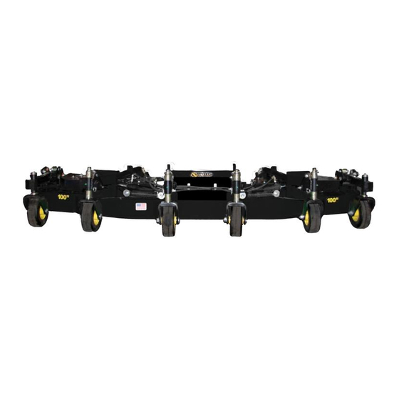
- Page 1 100EFD Lastec Mower (100EFD1565 & 100EFD1570/1580) Owner’s Manual Manual Part #: Man-100EFD...
- Page 2 Lastec, 2018 Printed in the United States of America, all rights reserved. No part of this manual may be reproduced in any form by any photographic, electronic, mechanical or other means or used in any information storage and retrieval system without written permission from Lastec, LLC 8180 W.
-
Page 3: Table Of Contents
Read This Manual BEFORE Operating The Articulator .......... 1-2 Product Registration ....................1-3 If You Need To Order Parts ..................1-3 Lastec Product Warranty ................... 1-4 Component Manufacturers’ Warranties ..............1-6 Servicing The Articulator ..................1-6 Warranty Registration ....................1-7... - Page 4 Model 100EFD Articulator Specifications..............5-4 Model 100EFD Articulator Maintenance Chart ............5-5 5.10 Torque Values ......................5-6 5.11 Lubrication Points ..................... 5-7 5.12 Electrical Schematics (100EFD1565 Only) .............. 5-8 5.13 Electrical Schematics (100EFD1570/1580 Only) ........... 5-11 5.14 Urethane Bushings....................5-15 Lastec//021819 Table of Contents...
-
Page 5: To The Owner
SECTION 1 TO THE OWNER Lastec//021819... -
Page 6: Read This Manual Before Operating The Articulator
Keep this manual on hand at all times for ready reference. The designed and tested safety of the Articulator is dependent upon its operation within the guidelines and limita- tions outlined in this manual. Always adhere to all the safety rules presented in this man- ual. Lastec//021819 To The Owner... -
Page 7: Product Registration
These numbers can be found on the serial number plate which is permanently affixed to the mower. You should now fill out the warranty registration form online at www.lastec.com or located in the back of this section. This form must be completed and returned to the fac- tory within fifteen (15) days of purchase in order to validate the warranty. -
Page 8: Lastec Product Warranty
Lastec Product Warranty LASTEC LIMITED GOLF & TURF WARRANTY Lastec (“warrantor”), with its place of business at 8180 W. 10th Street, Indianapolis, IN 46214 war- rants as stated herein to the original purchaser (“purchaser”) for two (2) years or 2000 hours* of equipment use, whichever comes first, on parts and one (1) year of labor for equipment use from the date of purchase from Lastec (“warrantor”), that the equipment manufactured by warrantor and... - Page 9 Warranty Parts Return Lastec reserves the right to have parts returned that have been submitted for warranty. The ser- vice department will issue an RMA number. The part must be returned within 30 days of the requested return date. Parts not returned within 30 days of the RMA issue date will result in rejec- tion of claim.
-
Page 10: Component Manufacturers' Warranties
Lastec parts, and has trained mechanics on hand. Be sure to complete the following Lastec Warranty Registration Form and return to Lastec within 15 days of the purchase of the Articulator. This will aid you, Lastec, and Lastec dis- tributor in warranting and servicing of your Articulator. -
Page 11: Warranty Registration
How did you hear about Lastec? Who referred you to Lastec? Who was the salesman that assisted you? Please check the box to your left if you would not allow Lastec to use your company's name for marketing purposes. To The Owner Lastec//021819... -
Page 13: Safety Information
Safety Information SECTION 2 SAFETY INFORMATION Safety Information Lastec//021819... -
Page 14: Warning Symbols
Safety Decals and Symbols The following safety symbols are used on the deck. Operators should become familiar with these symbols and heed the warnings where they appear on the deck. Attention! Pinching/Crushing Danger! Lastec//021819 Safety Information... - Page 15 Safety Information Safety Decals and Symbols Caution! Rotating Blades! Keep Hands and Feet Away from Blades! Keep Covers Locked Down Pinch Point! Read the Manual! Remove the Key! Rotating Parts! Rotating Shaft! Stay Away! Thrown Objects! Safety Information Lastec//021819...
-
Page 16: About This Manual
The illustrations and data used in this manual were current at the time of printing, but the deck may vary slightly due to ongoing engineering changes. Lastec reserves the right to implement engineering and design changes to the deck as may be necessary without prior notification. -
Page 17: Safety Guards And Covers
Safety is a primary concern in the design and manufacture of all Lastec products. Unfor- tunately, our extensive efforts to provide safe equipment can be negated by a single care- less act of an operator. -
Page 18: Pre-Operational Safety Rules
Verify that the deck is properly mounted, set up, adjusted, and in good operating condition. Always perform the pre-operation equipment inspection and the appropriate mainte- nance schedule (Section 5) before operating the deck. Do not change the engine governor settings or over-speed the engine. Lastec//021819 Safety Information... -
Page 19: Operational Safety Rules
Be sure that all auxiliary equipment switches (blades, lights, etc.) are in the OFF position before attempting to start the engine. Be sure your drive unit is equipped with a ROPS (Roll Over Protection System), and be sure to wear your seat belt. Safety Information Lastec//021819... - Page 20 Never adjust the mower deck height or lift the deck into transport position while the blades are engaged. Never engage the blades with the mower decks raised into transport position. Never place your hands or feet under the deck while the engine is running. Lastec//021819 Safety Information...
- Page 21 Do not allow extended running of drive unit engine indoors - exhaust fumes are deadly. Safety Information Lastec//021819...
-
Page 22: Maintenance Safety Rules
Verify that all warning labels and decals are properly installed, visible, and legible. Always remove debris from the top and bottom of the deck after each use. 2-10 Lastec//021819 Safety Information... -
Page 23: Storage Safety Rules
Sand chipped or scratched areas and re-paint them to prevent rust during storage. Lubricate all moving parts of the drive unit and deck to prevent rust during storage. Always remove the PTO shaft for storage. Always lock the safety pins on the raised decks. Safety Information Lastec//021819 2-11... -
Page 24: Hazard Identified Chart
Danger of projectile strike Ejected debris from cutting Warning decals. blades Clear warning in manual. Physical guards around blades. Finger pinch points Moving parts Warning decals stating hazardous loca- tions. Physical guards around such points. Clear warning in manual. 2-12 Lastec//021819 Safety Information... -
Page 25: Initial Set-Up
SECTION 3 INITIAL SET-UP Lastec//021819... -
Page 26: Assembly Instructions
Danger WARNING! DO NOT INSTALL OR USE a Lastec Model 100EFDC Articulator mower deck on a front mower with a cab if the side cutting decks in the raised transport position inter- Warning fere with the cab doors. - Page 27 14. Install the Quik-Tatch Weight Assembly to the tractor as recommended by John Deere. NOTE: Use four (4) R66949 4x42 Quick-Tatch Weights and TCB10303 Rear Weight Mount Kit with the 100EFD1565 Articulator. Use six (6) R66949 6x42 Quick-Tatch Weights and TCB10303 Rear Weight Mount Kit with the 100EFD1570/1580 Articulator. Initial Setup Lastec//021819...
-
Page 28: Step Installation
3. Install the step weldment to the underside of the frame behind the left drive wheel. 4. Use the provided fasteners to secure the step weldment to the traction unit. Step Pad Step Pad Step Weldment Step Weldment 100_227 Lastec//021819 Initial Setup... -
Page 29: Push Arm Adjustment
If necessary, lower the Articulator and readjust the jam nut on the weight transfer rod weldment to increase or decrease the clearance between the tire and the rubber grass chute. Initial Setup Lastec//021819... -
Page 30: Wire Harness Installation (100Efd1565 Only)
1. Lift the seat assembly on the tractor to access the battery compartment. 2. Disconnect the existing wire harness from the harness connector located next to the bat- tery as shown below. TOP VIEW Existing Wire Harness 100_043 Existing Wire Harness Seat Assembly Harness Connector Battery Lastec//021819 Initial Setup... - Page 31 Secure the wire harness to the tractor with wire ties. 6. Connect the plug on the provided wire harness to the socket on the wire harness from the Articulator. Initial Setup Lastec//021819...
-
Page 32: Wire Harness Installation (100Efd1570/1580 Only)
2. Locate the pink wire #760 connecting the PTO switch to the K1 Terminal of the PTO Knob (Open/VBat) on the Vehicle Control Unit (VCU). 100_234 Splice Here Splice Here 3. Splice the pink wire #760 as shown in the diagram above. Lastec//021819 Initial Setup... - Page 33 6. Connect the black/white ground wire from the electrical kit to the frame ground stud as shown above. IMPORTANT! To connect the wire, remove the nut, add the black/white ground wire ring terminal and reinstall the nut leaving all existing ring terminals in the order in which they were found. Initial Setup Lastec//021819...
- Page 34 PTO switch side here harness side here harness side here IMPORTANT! If the deck is removed from the traction unit, it is necessary to undo Step 9 for the PTO to function properly with any other attachment. 3-10 Lastec//021819 Initial Setup...
-
Page 35: Lift Arm Stop Bolt Adjustment
4. Slowly raise the unit to the transport position. Be sure the drive line does not contact the mower deck. If it does, lower the unit to the ground and slightly decrease the distance between the stop bolt head and the edge of the plate. Recheck for clearance. Initial Setup Lastec//021819 3-11... -
Page 36: Limit Switch Adjustment
Safety Pin in Unlocked Position 100_102 When transporting the mounted deck, the front wheel should be minimum of 4 inches off the ground, and 6 inches is preferred. Adjust the hitch as necessary to accomplish this elevation. 3-12 Lastec//021819 Initial Setup... -
Page 37: Pto Shaft Range Verification
PTO. You will need to either install a longer PTO shaft, or avoid this area when cutting. 11. If installing a longer PTO shaft, re-check your maximum PTO shaft compression. Initial Setup Lastec//021819 3-13... -
Page 38: Gearbox
Example: (1) 1” spacer and (2) 1/4” spacers placed below the wheel yoke collars will set the mower deck to 2-1/2”. 100_107 3-14 Lastec//021819 Initial Setup... -
Page 39: Mower Deck Leveling Adjustment
The leveling on the front yokes was preset at the factory, and should not need adjustment. In case of accident or equipment damage, additional or replacement spacers may be obtained from your Lastec dealer, if necessary. -
Page 40: Deck Drive Belts
The spring-loaded idler automatically tensions the belts. Check the belts for visible wear or damage. If either belt appears excessively worn, dam- aged, cracked, weathered, or otherwise appears to pose an unsuitable or unsafe operat- ing condition, replace the belt. 3-16 Lastec//021819 Initial Setup... - Page 41 Contact your Lastec distributor for the proper belt lengths for your Articulator. Be sure that the idler tensioning spring is properly installed and in good condition. If for some reason this spring becomes loose, detached, or fatigued, the idler will not properly tension the belts.
-
Page 42: Deck Belts And Alignment
If the belt you are check- ing is new, and the idler tensioner pivots to its maximum stroke without adequately tightening the belt, it is likely you have installed the wrong size belt. Contact your Lastec dealer for the proper belt lengths for your Articulator. -
Page 43: Blades
Always replace any damaged, dull, or missing blades before operating the Articulator. The rec- ommended torque value for the blade bolts is 75 ft/lbs. Contact your Lastec distributor for further information about optional blades available. Initial Setup Lastec//021819... -
Page 44: Deck Wheels
Check that the discharge chute is clear of debris, properly mounted, and in good condi- tion. Inspect entire Articulator for loose or entangled parts, debris, obstructions, neglected tools, or any other possible safety hazards, equipment hazards or projectile hazards. 3-20 Lastec//021819 Initial Setup... -
Page 45: Pre-Operation Equipment Inspection Checklist
Inspect entire Articulator for loose or entangled parts, debris, obstructions, or neglected tools. Perform all safety, set-up, and pre-operation procedures listed in your tractor manual. Complete the appropriate maintenance checklist (section 5). Initial Setup Lastec//021819 3-21... -
Page 47: Operating Procedures
SECTION 4 OPERATING PROCEDURES Lastec//021819... -
Page 48: Transporting The Articulator
To lift the deck for storage or transport when the deck is detached from the drive unit, use the lift brackets as shown below. NOTE: Always fold up the two outside decks for easy transportation and use the safety pins to lock the outside decks in the upright position. Lift Bracket Lift Bracket 100_105 Lastec//021819 Operating Procedures... -
Page 49: Hydraulic Lift Operation
Damage to equipment, serious personal injury, or fatal injury can result! The Articulator mowing decks come leveled from the Lastec factory. Should deck leveling be necessary during maintenance, see the section on Mower Deck Leveling Adjustment in the Set-Up section of this manual. -
Page 50: Preparation For Cutting
Complete the Initial Set-Up section of this manual BEFORE attempting to operate the Articulator. After transporting to the work area, remove the deck safety cables and lower the Articulator into cutting position. Be sure the Articulator is not positioned over any debris or loose objects. Lastec//021819 Operating Procedures... -
Page 51: Recommended Blades
The Low Lift Blade will also help reduce cutter deck blowout during the conditions stated above. High-Lift Blade (Part No. P128) High-Lift Blade is recommended for cool season grasses and cut heights of 2” and above, unless in sandy conditions. These blades are shipped standard on all mowers. Operating Procedures Lastec//021819... -
Page 52: Ground Speed
If you are not familiar with backing techniques, practice in an open area to develop the required skills before operating the Articulator. When backing up with the articulator, with the blades on or off, you must carefully watch Lastec//021819 Operating Procedures... -
Page 53: Cutting Extreme Contours
If, when cutting excessively wet or tall grass at reduced ground speed, you still do not get adequate grass discharge, consider making two passes over the area. Operating Procedures Lastec//021819... -
Page 54: Anti-Scalp Wheel Adjustment
Deck Height < 2” = Set the anti-scalp wheels to the top hole, Deck Height 2” to 3” = Set the anti-scalp wheels to the center hole, Deck Height > 3” = Set the anti-scalp wheels to the bottom hole. Lastec//021819 Operating Procedures... -
Page 55: Maintenance
SECTION 5 MAINTENANCE Lastec//021819... -
Page 56: Every 8 Operating Hours
Inspect entire Articulator for loose or entangled parts, debris, obstructions, mis- placed tools, or any other possible safety hazards, equipment hazards or projectile hazards. Clean off decks of any dirt, grease or oil. Clean and gauge wheels to reset the bearing pre-loads. (Reference Service Bulletin SB-0149) Lastec//021819 Maintenance... -
Page 57: First 8 Hours
Check and clean, if necessary, any debris that may have accumulated during operation. Check gearbox lube level and condition. Every 200 Operating Hours Change the gearbox oil (6 ounces SAE 75W-90 Grade gear oil). Maintenance Lastec//021819... -
Page 58: Every 500 Operating Hours
Red, 12 oz. Spray Can P229 Black, 12 oz. Spray Can L07467 Gearbox Gearbox, Superior R100 9AAB - B0216 028767 Gearbox Oil 6 Ounces SAE 75W-90 Grade Gear Oil PTO Shaft Bondioli DS1N066US000001 049617 PTO Shaft Assembly, Deere 26” Lastec//021819 Maintenance... -
Page 59: Model 100Efd Articulator Maintenance Chart
Inspect All Blade Spindle Bearings for Wear, Damage, Debris, & Proper Installation Re-pack All Wheel Bearings Inspect All Component Parts And Wear Points Replace gearbox shaft seals * First 8 hours, then every 50 after that. ** First 50 hours, then every 200 afer that. Maintenance Lastec Mowers/021819... -
Page 60: Torque Values
195 (264.4) ft-lbs (Nm) 160 (217.0) 210 (284.8) ft-lbs (Nm) 170 (230.5) 220 (298.3) ft-lbs (Nm) 175 (237.3) 225 (305.1) ft-lbs (Nm) 302 (409.5) 473 (640.9) ft-lbs (Nm) 300 (406.8) 400 (542.4) ft-lbs (Nm) 466 (631.8) 714 (967.4) Lastec//021819 Maintenance... -
Page 61: Lubrication Points
Maintenance Lubrication Points 5.11 Lubrication Points See Figure 5-1. The Articulator lubrication points are shown below. 100_051 IMPORTANT! Each wheel also has a fitting to be greased every 8 hours of operation. Maintenance Lastec//021819... -
Page 62: Electrical Schematics (100Efd1565 Only)
Maintenance Electrical Schematics (100EFD1565 Only) 5.12 Electrical Schematics (100EFD1565 Only) See Figure 5-2. The electrical schematics for the 100EFD1565 Lastec Mower are shown below. Lastec//021819 Maintenance... - Page 63 Maintenance Electrical Schematics (100EFD1565 Only) Maintenance Lastec//021819...
- Page 64 Maintenance Electrical Schematics (100EFD1565 Only) 5-10 Lastec//021819 Maintenance...
-
Page 65: Electrical Schematics (100Efd1570/1580 Only)
Maintenance Electrical Schematics (100EFD1570/1580 Only) 5.13 Electrical Schematics (100EFD1570/1580 Only) See Figure 5-3. The electrical schematics for the 100EFD1570/1580 Lastec Mower are shown below. Lt Blu Lt Blu Pnk (760) Pnk (760) To ECU Ylo (516) Tractor Control Circuit (Shown For Clarity) - Page 66 Maintenance Electrical Schematics (100EFD1570/1580 Only) 5-12 Lastec//021819 Maintenance...
- Page 67 Maintenance Electrical Schematics (100EFD1570/1580 Only) Maintenance Lastec//021819 5-13...
- Page 68 Maintenance Electrical Schematics (100EFD1570/1580 Only) 5-14 Lastec//021819 Maintenance...
-
Page 69: Urethane Bushings
CAUTION! Bolts holding urethane bushings must remain tight. Caution Urethane bushings are used Spacer must be throughout all Lastec mowers drawn tight in various applications, includ- framework by bolt ing (but not limited to) articu- lating deck hinges and rocker Spacer arms.
Need help?
Do you have a question about the 100EFD Series and is the answer not in the manual?
Questions and answers