
Related Manuals for Lastec 100EZT


Summary of Contents for Lastec 100EZT
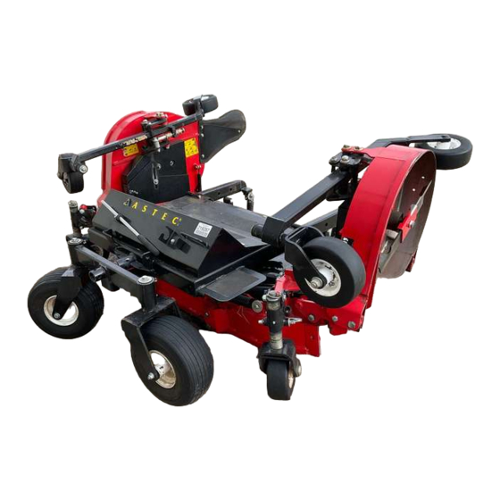
- Page 1 LASTEC DECK KIT 100EZT Owner’s Manual Manual Part #: Man-100EZT ASTEC 7865 N County Road 100E Lizton, Indiana 46149 Phone (317) 892-4444 Fax (317) 892-4188 www.lastec.com...
- Page 2 Lastec, 2009 Printed in the United States of America, all rights reserved. No part of this manual may be reproduced in any form by any photographic, electronic, mechanical or other means or used in any information storage and retrieval system without written permission from Lastec, Inc.
-
Page 3: Table Of Contents
Read This Manual BEFORE Operating The Articulator .......... 1-2 Product Registration ....................1-3 If You Need To Order Parts ..................1-3 Lastec Product Warranty ................... 1-4 Component Manufacturers’ Warranties ..............1-6 Servicing The Articulator ..................1-6 Warranty Registration ....................1-7... - Page 4 Every 500 Operating Hours..................5-3 Annual ........................5-4 Model 100ETZ Deck Specifications ................. 5-4 Model 100ETZ Deck Maintenance Chart ..............5-5 5.10 Torque Values ......................5-6 5.11 Lubrication Points ..................... 5-7 5.12 Electrical Schematic ....................5-8 5.13 Urethane Bushings..................... 5-9 Lastec//020515 Table of Contents...
-
Page 5: To The Owner
SECTION 1 TO THE OWNER Lastec//020515... -
Page 6: Read This Manual Before Operating The Articulator
Keep this manual on hand at all times for ready reference. The designed and tested safety of the Articulator is dependent upon its operation within the guidelines and limita- tions outlined in this manual. Always adhere to all the safety rules presented in this man- ual. Lastec//020515 To The Owner... -
Page 7: Product Registration
These numbers can be found on the serial number plate which is permanently affixed to the mower. You should now fill out the warranty registration form online at www.lastec.com or located in the back of this section. This form must be completed and returned to the fac- tory within fifteen (15) days of purchase in order to validate the warranty. -
Page 8: Lastec Product Warranty
Lastec Product Warranty LASTEC LIMITED GOLF & TURF WARRANTY Lastec (“warrantor”), with its place of business at 7865 N. County Road 100E, Lizton, IN 46149 warrants as stated herein to the original purchaser (“purchaser”) for two (2) years or 2000 hours* of equipment use, whichever comes first, on parts and one (1) year of labor for equipment use from the date of purchase from Lastec (“warrantor”), that the equipment manufactured by warran-... - Page 9 Warranty Parts Return Lastec reserves the right to have parts returned that have been submitted for warranty. The ser- vice department will issue an RMA number. The part must be returned within 30 days of the requested return date. Parts not returned within 30 days of the RMA issue date will result in rejec- tion of claim.
-
Page 10: Component Manufacturers' Warranties
Lastec parts, and has trained mechanics on hand. Be sure to complete the following Lastec Warranty Registration Form and return to Lastec within 15 days of the purchase of the Articulator. This will aid you, Lastec, and Lastec dis- tributor in warranting and servicing of your Articulator. -
Page 11: Warranty Registration
How did you hear about Lastec? Who referred you to Lastec? Who was the salesman that assisted you? Please check the box to your left if you would not allow Lastec to use your company's name for marketing purposes. To The Owner Lastec//020515... -
Page 13: Safety Information
Safety Information SECTION 2 SAFETY INFORMATION Safety Information Lastec//020515... -
Page 14: Warning Symbols
Safety Decals and Symbols The following safety symbols are used on the deck. Operators should become familiar with these symbols and heed the warnings where they appear on the deck. Attention! Pinching/Crushing Danger! Lastec//020515 Safety Information... - Page 15 Safety Information Safety Decals and Symbols Caution! Rotating Blades! Keep Hands and Feet Away from Blades! Keep Covers Locked Down Pinch Point! Read the Manual! Remove the Key! Rotating Parts! Rotating Shaft! Stay Away! Thrown Objects! Safety Information Lastec//020515...
-
Page 16: About This Manual
The illustrations and data used in this manual were current at the time of printing, but the deck may vary slightly due to ongoing engineering changes. Lastec reserves the right to implement engineering and design changes to the deck as may be necessary without prior notification. -
Page 17: Safety Guards And Covers
Safety is a primary concern in the design and manufacture of all Lastec products. Unfor- tunately, our extensive efforts to provide safe equipment can be negated by a single care- less act of an operator. -
Page 18: Pre-Operational Safety Rules
Verify that the deck is properly mounted, set up, adjusted, and in good operating condition. Always perform the pre-operation equipment inspection and the appropriate mainte- nance schedule (Section 5) before operating the deck. Do not change the engine governor settings or over-speed the engine. Lastec//020515 Safety Information... -
Page 19: Operational Safety Rules
Be sure that all auxiliary equipment switches (blades, lights, etc.) are in the OFF position before attempting to start the engine. Be sure your drive unit is equipped with a ROPS (Roll Over Protection System), and be sure to wear your seat belt. Safety Information Lastec//020515... - Page 20 Never adjust the mower deck height or lift the deck into transport position while the blades are engaged. Never engage the blades with the mower decks raised into transport position. Never place your hands or feet under the deck while the engine is running. Lastec//020515 Safety Information...
- Page 21 Do not allow extended running of drive unit engine indoors - exhaust fumes are deadly. Safety Information Lastec//020515...
-
Page 22: Maintenance Safety Rules
Verify that all warning labels and decals are properly installed, visible, and legible. Always remove debris from the top and bottom of the deck after each use. 2-10 Lastec//020515 Safety Information... -
Page 23: Storage Safety Rules
Sand chipped or scratched areas and re-paint them to prevent rust during storage. Lubricate all moving parts of the drive unit and deck to prevent rust during storage. Always remove the PTO shaft for storage. Always lock the safety pins on the raised decks. Safety Information Lastec//020515 2-11... -
Page 24: Hazard Identified Chart
Danger of projectile strike Ejected debris from cutting Warning decals. blades Clear warning in manual. Physical guards around blades. Finger pinch points Moving parts Warning decals stating hazardous loca- tions. Physical guards around such points. Clear warning in manual. 2-12 Lastec//020515 Safety Information... -
Page 25: Initial Set-Up
Initial Set-Up SECTION 3 INITIAL SET-UP Initial Set-Up Lastec//091812... -
Page 26: Assembly Instructions
Assembly Instructions Assembly Instructions The Lastec Deck Kit 100ETZ is shipped on a separate pallet from the Toro 30381 drive unit. Unpack the Toro 30381 drive unit and lift the unit from the pallet using an overhead hoist. Unpack the Lastec deck kit and remove the drive unit wheels from the pallet. Install the wheels to the drive unit. - Page 27 IMPORTANT: It can be easier to remove the hydraulic hose attached to the inner side of the foot valve (supplied by Lastec) and install it to the drive unit hydraulic pump before installing the mower deck to the drive unit.
- Page 28 Route the hose supplied with the Toro drive unit to the foot valve. Connect the hose to the fitting on the outer side of the foot valve as shown below. SIDE VIEW FRONT VIEW Foot Valve Hose Supplied by Toro Existing Hose Foot Valve Supplied by Lastec TR1028 Existing Hose Supplied by Lastec Lastec//091812 Initial Set-Up...
- Page 29 Initial Set-Up Assembly Instructions Route the hose attached to the inner side of the foot valve (supplied by Lastec) to the hydraulic pump located on the drive unit. Connect the hose to the bottom of the hydraulic pump. (Remove any existing hoses or fittings that may be installed there.)
- Page 30 TR1030 Rear Mount Guard Plate Electrical Installation Lift the operator seat to access the Hydraulic hydraulic valve compartment. Locate Tank the existing connectors next to the hydraulic tank. Disconnect the connec- tors. Existing Connectors TR1031 Lastec//091812 Initial Set-Up...
-
Page 31: Transporting The Mounted Deck
If the oil appears excessively contaminated, change the gearbox oil -- 12 oz. of SAE EP90 (80W-90). Inspect the entire area around and under the gearbox for any oil leakage. If a leak is dis- covered, repair it and refill the gearbox before operating the deck. Initial Set-Up Lastec//091812... -
Page 32: Mower Deck Height Adjustment
Handle adjustment rod has one (1) permanently fixed spacer, twelve (13) adjust- able spacers, each equal to 1/4” of deck height adjustment. Parts removed for illustration purposes Always operate with covers in place Lastec//091812 Initial Set-Up... - Page 33 In case of accident or equipment damage, addi- tional or replacement spacers may be obtained from your Lastec dealer, if necessary. 5. Adjust the rear wheel lock spacers to remove any excess slack by loosening the jam nut, adjusting the rod on wheel lock arm until any slack in the rod is taken up, and then tight- ening the jam nut.
-
Page 34: Deck Belts And Alignment
If you are unable to install a new belt with the idler system at its minimum stroke, it is likely you are installing the wrong size belt. Contact your Lastec dealer for proper belt lengths for your deck. -
Page 35: Blades
Always replace any damaged, dull, or missing blades before operating the deck. The recom- mended torque value for the blade bolts is 75 ft/lbs. Contact your distributor for further information about optional blades available. Initial Set-Up Lastec//091812 3-11... -
Page 36: Deck Wheels
Check that the discharge chutes are clear of debris, properly mounted, and in good condi- tion. Inspect entire deck for loose or entangled parts, debris, obstructions, neglected tools, or any other possible safety hazards, equipment hazards or projectile hazards. 3-12 Lastec//091812 Initial Set-Up... -
Page 37: 3.10 Pre-Operation Equipment Inspection Checklist
Inspect entire deck for loose or entangled parts, debris, obstructions, or neglected tools. Perform all safety, set-up, and pre-operation procedures listed in your drive unit man- ual. Complete the appropriate maintenance checklist (section 5). Initial Set-Up Lastec//091812 3-13... -
Page 39: Operating Procedures
Operating Procedures SECTION 4 OPERATING PROCEDURES Operating Procedures Lastec//020515... -
Page 40: Transporting The Deck
The 100ETZ deck mowing decks come leveled from the factory. Should deck leveling be necessary during maintenance, see the section on Mower Deck Leveling Adjustment in the Set-up section of this manual. 1. Disengage the PTO. Wait for all motion to stop. 2. Slowly engage the hydraulics. Lastec//020515 Operating Procedures... -
Page 41: Preparation For Cutting
The deck offers a high level of maneuverability. Although the deck is an industrial-quality mower, do not attempt to use it to cut extremely long grass or areas heavy with brush or debris. Operating Procedures Lastec//020515... - Page 42 If the deck appears to be operating correctly, slowly increase the drive unit engine speed until the PTO shaft is operating at the drive unit manufacturer's recom- mended operating RPM. DO NOT EXCEED THIS RPM DURING OPERATION OF THE DECK. Release the parking brake and carefully begin cutting. Lastec//020515 Operating Procedures...
-
Page 43: Recommended Blades
Gator Mulching Blade (Part No. P322 for 21” Blade and P848 for 25” Blade) Mulching blades are designed for use with a mulching (discharge block-off) plate or with a complete mulching system. These blades feature a high lift, “double-cut” edge for quick, thorough shredding of grass clippings, leaves and debris. Operating Procedures Lastec//020515... -
Page 44: Ground Speed
When backing up with the deck, with the blades on or off, you must carefully watch the area around the deck for obstacles, people, pets and anything that the machine could come into contact with. Lastec//020515 Operating Procedures... -
Page 45: Cutting Extreme Contours
If, when cutting excessively wet or tall grass at reduced ground speed, you still do not get adequate grass discharge, consider making two passes over the area. Operating Procedures Lastec//020515... -
Page 47: Maintenance
Maintenance SECTION 5 MAINTENANCE Maintenance Lastec//091812... -
Page 48: Every 8 Operating Hours
Clean off decks of any dirt, grease or oil. Perform the appropriate maintenance procedures listed in your drive unit manual. Verify proper installation, operation and flow of grass chutes. Lastec//091812 Maintenance... -
Page 49: First 8 Hours
Inspect all blade spindle bearings for wear or damage. Replace if needed. Inspect and re-pack all wheel bearings. Replace if needed. Inspect all component parts and wear points. Repair or replace any worn, damaged, or missing parts. Maintenance Lastec//091812... -
Page 50: Annual
9” x 3” solid, white rim 061826 Mower Drive Deck Belt (1) Belt, B165 Main Drive 059707 Mower Deck Belt (2) Belt, Insta-Power 85830 (Outer decks) 041630 Gearbox Comer Industries 059294 Gearbox Oil 12 oz. of SAE EP90 (80W-90) Lastec//091812 Maintenance... -
Page 51: Model 100Etz Deck Maintenance Chart
Inspect All Blade Spindle Bearings for Wear, Damage, Debris, & Proper Installation Re-pack All Wheel Bearings Inspect All Component Parts And Wear Points Replace gearbox shaft seals * First 8 hours, then every 50 after that. ** First 50 hours, then every 200 afer that. Maintenance Lastec Mowers/091812... -
Page 52: 5.10 Torque Values
195 (264.4) ft-lbs (Nm) 160 (217.0) 210 (284.8) ft-lbs (Nm) 170 (230.5) 220 (298.3) ft-lbs (Nm) 175 (237.3) 225 (305.1) ft-lbs (Nm) 302 (409.5) 473 (640.9) ft-lbs (Nm) 300 (406.8) 400 (542.4) ft-lbs (Nm) 466 (631.8) 714 (967.4) Lastec//091812 Maintenance... -
Page 53: 5.11 Lubrication Points
Maintenance Lubrication Points 5.11 Lubrication Points See Figure 5-1. The Articulator lubrication points are shown below. 100_052 IMPORTANT! Each wheel also has a fitting to be greased every 8 hours of operation. Maintenance Lastec//091812... -
Page 54: 5.12 Electrical Schematic
Maintenance Electrical Schematic 5.12 Electrical Schematic Black Lastec//091812 Maintenance... -
Page 55: 5.13 Urethane Bushings
CAUTION! Bolts holding urethane bushings must remain tight. Caution Urethane bushings are used Spacer must be throughout all Lastec mowers drawn tight in various applications, includ- framework by bolt ing (but not limited to) articu- lating deck hinges and rocker Spacer arms.
Need help?
Do you have a question about the 100EZT and is the answer not in the manual?
Questions and answers