Table of Contents
Advertisement
Quick Links
Advertisement
Table of Contents

Subscribe to Our Youtube Channel
Related Manuals for IFM N0530A


Summary of Contents for IFM N0530A
- Page 1 Operating instructions Switching amplifiers N0530A N0533A...
- Page 2 Contents 1 Preliminary note ..................... 3 2 Safety instructions..................3 3 Intended use ....................3 Classification................... 4 ATEX certificate ..................4 IECEx certificate ..................4 Identification.................... 4 4 Installation...................... 4 Requirements for cables and connection cables ........5 Requirements in case of use as associated equipment......5 5 Electrical connection ..................
- Page 3 1 Preliminary note You will find instructions, technical data, approvals and further information using the QR code on the unit / packaging or at www.ifm.com. 2 Safety instructions • The unit described is a subcomponent for integration into a system. – The system architect is responsible for the safety of the system.
- Page 4 The unit is an associated equipment according to IEC/EN 60079-11. The unit is not suitable for separating signals in power measurement technology. The unit transmits binary signals of NAMUR sensors or mechanical contacts from the hazardous area into the non-hazardous area. u Only use the unit within the permissible operating conditions.
- Page 5 The unit has the protection rating IP20 according to IEC/EN 60529. u Only install and use the unit under operating conditions that do not exceed soiling degree 2 according to IEC EN 60664-1. In case of use under operating conditions with a higher degree of soiling, the unit must be protected accordingly.
- Page 6 u If the unit is connected to intrinsically safe equipment, the upper limiting values of the unit must be observed. u If intrinsically safe units are connected to the intrinsically safe circuits of the corresponding equipment, the respective upper limiting values consistent with the explosion protection according to IEC/EN 60079-14 or IEC/EN 60079-25 must be observed (proof of intrinsic safety).
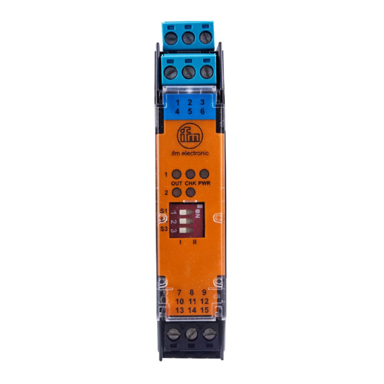
- Page 7 6 Operating and display elements Ι ΙΙ Ι ΙΙ 1: LED yellow Indication of the switching status output 1 / output 2; lights when the corresponding output is switched / the relay is en- ergised. 2: LED red Fault indication for input circuit 1 / input circuit 2; lights in case of wire break or short circuit in the respective input circuit.
- Page 8 6: Selector switch S3 Setting for short circuit / wire monitoring • When proximity sensors are connected monitoring is always active. S3 must be in position I. • When mechanical switches are connected the following applies: – Monitoring active for input circuit no. 1; S3 must be in position –...
Need help?
Do you have a question about the N0530A and is the answer not in the manual?
Questions and answers