Table of Contents
Advertisement
Quick Links
Advertisement
Table of Contents

Subscribe to Our Youtube Channel
Related Manuals for IFM efector200 OOF Series


Summary of Contents for IFM efector200 OOF Series
- Page 1 Operating instructions Switching amplifier for fibre optics...
-
Page 2: Table Of Contents
Contents 1 Function and features ������������������������������������������������������������������������������������������3 2 Operator interface ������������������������������������������������������������������������������������������������3 3 Installation������������������������������������������������������������������������������������������������������������4 3�1 Attaching the fibre optics �������������������������������������������������������������������������������4 3�1�1 Plastic fibre optics ���������������������������������������������������������������������������������5 3�1�2 Glass fibre optics ����������������������������������������������������������������������������������5 4 Operation �������������������������������������������������������������������������������������������������������������5 5 Initial setup�����������������������������������������������������������������������������������������������������������6 6 Operation display �������������������������������������������������������������������������������������������������6 7 Electrical connection ��������������������������������������������������������������������������������������������6 8 Basic settings�������������������������������������������������������������������������������������������������������6 8�1 Automatic setting of the switching threshold ��������������������������������������������������6 8�1�1 Setting with object ��������������������������������������������������������������������������������7... -
Page 3: Function And Features
The switching amplifier detects objects without contact and indicates the result with an output signal� • Type OOF���/KL for the connection of the ifm fibre optics types FE-11 and FT-11 (plastic fibre optics)� • Type OOF���/GL for the connection of the ifm fibre optics types FE-00 and FT-00 (glass fibre optics)�... -
Page 4: Installation
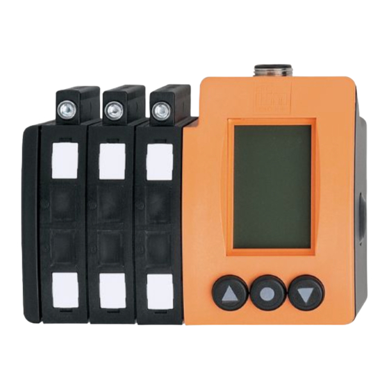
Typ OOF.../GL Glass fibre optics 1: connections glass fibre optic 2: display 3: pushbuttons 4: DIN-rail release 5: labels 6: LED These operating instructions show and describe the switching amplifier for 8 fibre optics as an example� The functions of the units with 2, 4 or 6 fibre optic connec- tions are identical, except for the number of channels�... -
Page 5: 3�1�1 Plastic Fibre Optics
3.1.1 Plastic fibre optics Push the fibres into the sensor holes until you feel a slight resistance (O-ring)� Push the fibres further until the stop (optic elements)� Turn the fastening screw to secure the fibres, max. torque 0.3 Nm. When dismantling the fibres first loosen the fastening screw�... -
Page 6: Initial Setup
If you do not activate any pushbutton for more than 5 min� the unit switches back to the operation display� 5 Initial setup First select the menu language� The following languages are available: German, English and French� Depending on the mounting position the display can be rotated by 180°� After these basic settings have been made the unit switches to the operation display��... -
Page 7: 8�1�1 Setting With Object
Select the channel to be set by pressing [▲] [▼] until the required channel is highlighted� In the figure channel 1 has been selected� Confirm the selection by pressing [●]. Select [Setup] from the menu and confirm the selection by pressing [●]. 1: light-on mode activated CH1 Lon (NO for diffuse reflection fibre optics... -
Page 8: 8�1�2 Setting Without Object
8.1.2 Setting without object CH1 Lon CH1 Lon ---- ---- Remove Measure object without Continue object.. When you have removed the object from the detection area of the optics or if objects are moving through the detection area, press [●] once. Now the measurement is carried out for approx�... -
Page 9: Extended Setting Options
9 Extended setting options 9.1 Setting of options Select the menu point [Options] in the channel display and confirm the selection by pressing [●]. CH1 Lon 1625 Setup Options Exit 1: selection light-on/dark-on mode CH1 Lon 2: off-delay can be set from 0 ��� 100 ms 3: 2 switch point for the activated channel (only available for channels... -
Page 10: 9�2 Programming Of The Output Function
9.2 Programming of the output function Select the function [Lon / Don] from the options. Lon = NO for diffuse reflection fibre optics and NC for through-beam fibre optics Don = NC for diffuse reflection fibre optics and NO for through-beam fibre optics CH1 Lon 1427 Light on... -
Page 11: 9�4 Setting The Pulse Stretching
The switching threshold can be modified by pressing [▲] or [▼]. Store the value by pressing [●]. For lower values the resolution of the switch point is finer� In that case the threshold value is displayed accordingly with two decimal places�� 9.4 Setting the pulse stretching Input signals shorter than the set time are extended to the set time (0���100 ms)�... -
Page 12: 9�5 Logic Functions
9.5 Logic functions After selecting the menu point [Logic] further selection options are displayed in a new window� Select the menu point [Set] for setting. CH1 Lon 1427 Delete Exit 1: channel which is combined with the CH1 Lon others 2: channel not combined 3: switching output channel 1 is combined OUT1... -
Page 13: 9�6 Second Switch Point For A Selected Channel (Only For Channels 1, 3, 5, 7)
By selecting the menu point „Exit“ you leave the selection window� Explanation of the example: The display shows that the switching output of channel 1 is logically combined AND with the switching output of channel 3 and that it is logically combined OR with the switching output of channel 5�... -
Page 14: Unit Options
10 Unit options If you select the menu point [Options] in the operation display and confirm by means of the [●] button, you get to the following menu points: Options Language Rotation Contrast Syst.-info Factory setting Fc output Exit [Language] Here you can select the menu language: German, English or French [Rotation] Depending on the mounting position the display can be rotated by 180°�... -
Page 15: Electronic Lock
11 Electronic lock The electronic lock is activated by simultaneously pressing [▲] [▼] for 10 s in the operating display mode� The electronic lock can be deactivated by simultaneously pressing [▲] [▼] for 10 s again in the operating display mode� You can see the current status of the electronic lock (lock open - lock closed) in the operation display�... -
Page 16: Error Messages
13 Error messages The error messages are reset automatically if the fault has been removed� The error message can be suppressed by selecting [Exit] - confirm. After about 2.5 min� the message appears again� Message Message Short Short circuit on circuit on switching function... -
Page 17: Socket
14 Socket M12 connector M16 connector 2 - 4 channels 6 - 8 channels Order No E11231 Order No E11645 Connection Connection 2 channels 4 channels 6 channels 8 channels out 1 out 1 out 1 out 1 out 2 out 2 out 2 out 2... -
Page 18: Wiring
15 Wiring 15.1 DC PNP 2 channels 4 channels Out 1 Out 2 4: Out 1 4: Out 1 2: Out 2 2: Out 2 5: Out 3 6: Out 4 7: Function check output 6 channels 8 channels E: Out 1 E: Out 1 P: Out 2 P: Out 2... -
Page 19: 15�2 Dc Npn
15.2 DC NPN 2 channels 4 channels Out 1 Out 2 4: Out 1 4: Out 1 2: Out 2 2: Out 2 5: Out 3 6: Out 4 7: Function check output 6 channels 8 channels E: Out 1 E: Out 1 P: Out 2 P: Out 2...
Need help?
Do you have a question about the efector200 OOF Series and is the answer not in the manual?
Questions and answers