Yamaha EF2400iS Owner's Manual
Hide thumbs
Also See for EF2400iS:
- Owner's manual (256 pages) ,
- Service manual (120 pages) ,
- Theory & diagnostics manual (218 pages)
Table of Contents
Advertisement
Quick Links
Advertisement
Table of Contents

Related Manuals for Yamaha EF2400iS


Summary of Contents for Yamaha EF2400iS
- Page 1 Generator OWNER’S MANUAL EF2400iS LIT-19626-01-23 7CF-28199-10...
- Page 3 AE00002 INTRODUCTION Congratulations on your purchase of your new Yamaha. This manual will provide you with a good basic understanding of the operation and main- tenance of this machine. If you have any questions regarding the operation or maintenance of your machine, please consult a Yamaha dealer.
- Page 4 Particularly important information is distin- guished in this manual by the following NOTE: notations. 9 Yamaha continually seeks advance- ments in product design and quality. Therefore, while this manual contains The Safety Alert Symbol means ATTEN- the most current product information...
-
Page 5: Table Of Contents
AE00041 CONTENTS PERIODIC MAINTENANCE ....20 LIMITED WARRANTY (EF- AND EDL-SERIES)..........1 MAINTENANCE CHART ....20 LOCATION OF IMPORTANT LABELS ..3 SPARK PLUG INSPECTION .....22 SAFETY INFORMATION ......5 CARBURETOR ADJUSTMENT..22 EXHAUST FUMES ARE ENGINE OIL REPLACEMENT ..23 POISONOUS ........5 MUFFLER SCREEN AND SPARK ARRESTER ........24 FUEL IS HIGHLY FLAMMABLE AND POISONOUS ........5... -
Page 6: Limited Warranty (Ef- And Edl-Series)
FOR A PARTICULAR PURPOSE WHICH EXCEED authorized Yamaha consumer generator dealer will, THE OBLIGATIONS AND TIME LIMITS STATED IN free of charge, repair or replace, at Yamaha’s THIS WARRANTY ARE HEREBY DISCLAIMED BY option, any part adjudged defective by Yamaha due YAMAHA MOTOR CORPORATION, U.S.A. - Page 7 Corporation, U.S.A. by the selling dealer at the time specified in the Owner’s Manual? of your purchase. If you should move after you have A. No. The warranty on a new Yamaha cannot be purchased your new generator, please advise us of “voided” or “cancelled.”...
-
Page 8: Location Of Important Labels
AE00062 LOCATION OF IMPORTANT LABELS Please read the following labels carefully before oper- ating this machine. NOTE: Maintain or replace safety and instruction labels, as necessary. 792-063 792-064 – 3 –... - Page 9 Rated Phase Single DC output Fuel Gasoline YAMAHA MOTOR CO., LTD. MADE IN JAPAN ***-24164-** ENGINE AIR INDEX ( C a l i f o r n i a onl y ) IMPORTANT ENGINE INFORMATION ENGINE FAMILY : zzzzzzzzzzzz REFER TO OWNER'S MANUAL FOR MAINTENANCE SPECIFICATIONS AND ADJUSTMENTS.
-
Page 10: Safety Information
AE00071 SAFETY INFORMATION AE00072 EXHAUST FUMES ARE POISONOUS 9 Never operate the engine in a closed area or it may cause unconsciousness and death within a short 741-112 time. Operate the engine in a well ventilated area. AE00075 FUEL IS HIGHLY FLAMMABLE AND POISONOUS 9 Always turn off the engine when refuelling. -
Page 11: Electric Shock Prevention
9 Keep the machine at least 1 m (3 ft) from buildings or other equipment, or the engine may overheat. a 1 m (3 ft) 741-118 9 Avoid operating the engine with a dust cover. 741-119 9 Be sure to carry the generator only by its carrying handle(s). -
Page 12: Connection Notes
Ground (earth) Lead Diameter: 0.12 mm (0.005 in)/ampere 10 Ampere → 1.2 mm (0.05 in) AE01181 CONNECTION NOTES 9 Avoid connecting the generator to commercial power outlet. 1 Correct 2 Incorrect AE00091 CONNECTION Before the generator can be connected to a build- ing’s electrical system, a licensed electrician must install an isolation (transfer) switch in the build- ing’s main fuse box. -
Page 13: Control Function
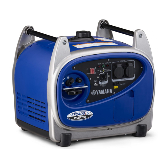
AE00101 CONTROL FUNCTION AE00102 DESCRIPTION 1 Carrying handles (shaded) 2 Fuel level gauge 3 Fuel tank cap 4 Oil filler cap 5 Recoil starter 6 Fuel cock 7 Muffler 793-146 AE00103 CONTROL PANEL 1 Engine switch 2 Twin Tech (parallel running terminal) 3 DC protector 4 Oil warning light 5 AC pilot light... -
Page 14: Oil Warning System
FOR PARALLEL RUNNING ) This is the terminal for connecting special cables for par- allel running of two EF2400iS. The parallel running requires two EF2400iS and the special cables. (The rated output in parallel running is 3.6 kVA and the rated current is 30.0 A.) -
Page 15: Pre-Operation Check
Fuel tank capacity: 707-033c Total: 6.0 L (1.32 Imp gal, 1.59 US gal) Your Yamaha engine has been designed to use regular unleaded gasoline with a pump octane number ((R + M)/2) of 86 or higher, or research octane number of 91 or higher. -
Page 16: Engine Oil
AE00222 ENGINE OIL Make sure the engine oil is at the upper level of the oil filler hole. Add oil as necessary. 700-128 1 Upper level Recommended oil: å YAMALUBE 4 (10W-30) or SAE 10W-30 type SE motor oil ∫ SAE #30 ç... -
Page 17: Operation
AE00955 OPERATION NOTE: The generator has been shipped without engine oil. Fill with oil or it will not start. 700-006a 1 Upper level AE01171 STARTING THE ENGINE NOTE: 9 Before starting the engine, do not connect any 761-085 electric devices. 1. - Page 18 4. Pull slowly on the recoil starter until it is engaged, then pull it briskly. 5. After the engine starts, warm up the engine until the engine does not stop when the choke knob is returned to the original position. 704-019 6.
-
Page 19: Application Range
AE01180 APPLICATION RANGE 0.4–0.75 Power factor 0.8–0.95 (Efficiency 0.85) Rated voltage EF2400iS –2,000W –1,600W –680W Rated current NOTE: 9 “–” means below. 9 Application wattage indicates when each device is used by itself. 9 The overload indicator light 1 comes on when total wattage exceeds the application range. -
Page 20: Connection
AE01172 CONNECTION Alternating Current (AC) 9 Be sure all electric devices including the lines and plug connections are in good condition before connection to the generator. 9 Be sure any electric devices are turned off before plugging it in. 9 Be sure the total load is within generator rated output. - Page 21 AE00788 Overload indicator light The overload indicator light 1 comes on when an over- load of a connected electrical device is detected, the inverter control unit overheats, or the AC output voltage rises. The electronic breaker will then activate, stopping power generation in order to protect the generator and 760-029 any connected electric devices.
- Page 22 9 Reduce the load to the specified generator rated output if the DC protector turns off. If it turns off again, consult a Yamaha dealer. NOTE: Press to reset the DC protector. 763-238a 1 “ON”...
- Page 23 Never smoke or make and break connections at the battery while charging. Sparks may ignite the bat- tery gas. Battery electrolyte is poisonous and dangerous, causing severe burns, etc. contains sulfuric (sul- phuric) acid. Avoid contact with skin, eyes or cloth- ing.
-
Page 24: Stopping The Engine
AE01173 STOPPING THE ENGINE NOTE: 9 Turn off any electric devices. 761-085 1. Disconnect any electric devices. 2. Turn the engine switch to the “5” (STOP) position. 5 “STOP” 763-262 3. Turn the fuel cock lever to “OFF”. 2 “OFF” 705-075a –... -
Page 25: Periodic Maintenance
Clean/ replace if necessary. Check oil level Engine Oil Replace Clean. Air Filter Replace if necessary. * : It is recommended that these items be serviced by a Yamaha dealer. ** : Related to emission control system. – 20 –... - Page 26 Fasteners Correct if necessary. * : It is recommended that these items be serviced by a Yamaha dealer. ** : Related to emission control system. Use only Yamaha specified genuine parts for replacement. Ask an authorized Yamaha dealer for further attention.
-
Page 27: Spark Plug Inspection
7. Install the side cover and tighten the bolt. AE00431 CARBURETOR ADJUSTMENT The carburetor is a vital part of the engine. Adjusting should be left to a Yamaha dealer with the professional knowledge, specialized data, and equipment to do so properly. – 22 –... -
Page 28: Engine Oil Replacement
AE01174 ENGINE OIL REPLACEMENT 1. Place the machine on a level surface and warm up the engine for several minutes. Then stop the engine. 2. Remove the rubber cap 1 on the bottom. 700-130 3. Place an oil pan under the engine . Remove the drain bolt 2. -
Page 29: Muffler Screen And Spark Arrester
Recommended oil: 0°C 25°C å YAMALUBE 4 (10W-30) or SAE 10W-30 type SE motor oil A YAMALUBE 4(10W-30) ∫ SAE #30 ç SAE #20 D SAE 10W C SAE #20 B SAE #30 ∂ SAE 10W Engine oil quantity: 32°F 80°F 0.6 L (0.53 Imp qt, 0.63 US qt) 700-065... - Page 30 3. Use a flathead screw driver to pry the spark arrester out from the muffler. 711-078 4. Remove the spark arrester. 1 Spark arrester 711-079 5. Remove the carbon deposits on the muffler screen and spark arrester using a wire brush. When cleaning, use the wire brush lightly to avoid damaging or scratching of the muffler screen and spark arrester.
-
Page 31: Air Filter
E01175 AIR FILTER 1. Loosen the bolt 1 and remove the cover 2. 788-017 2. Remove the air filter cover and element. 3. Wash the foam element in solvent and dry. 4. Oil the foam element and squeeze out excess oil. The foam element should be wet but not dripping. -
Page 32: Fuel Tank Filter
AE00471 FUEL TANK FILTER 1. Remove the fuel tank cap and filter. 1 Filter 2. Clean the filter with solvent. If damaged, replace. 3. Wipe the filter and insert it. Be sure the tank cap is tightened securely. 707-108 – 27 –... -
Page 33: Troubleshooting
AE01176 TROUBLESHOOTING Engine won’t start 1. Fuel systems No fuel supplied to combustion chamber. 2 No fuel in tank ..Supply fuel. 707-106 2 Fuel in tank ..Fuel cock lever to “ON”. 2 Clogged fuel line ..Clean fuel line. 2 Clogged carburetor .. - Page 34 Engine does not Engine starts. start. Check the following Clean or Replace; Consult O Clogged 9 Fuel line clogging Yamaha dealer. 9 Air cleaner element Consult a Yamaha dealer. clogging. – 29 –...
-
Page 35: Storage
AE00601 STORAGE Long term storage of your machine will require some preventive procedures to guard against deterioration. AE01177 DRAIN THE FUEL 1. Remove the fuel tank cap. Drain the fuel from the fuel tank into an approved gasoline container using a commercially available hand siphon. -
Page 36: Exhaust Emission Control System And Components
ROAD ENGINES. The acronyms conform to the latest version of the SAE’s recommended practice docu- ment J1930, “Diagnostic Acronyms, Terms, and Definitions For Electrical/Electronic System”. It is recommended that these items be serviced by a Yamaha dealer. – 31 –... -
Page 37: Specifications
AE00701 SPECIFICATIONS AE00702 DIMENSIONS Unit EF2400iS Overall Length mm (in) 527 (20.7) Overall Width mm (in) 419 (16.5) Overall Height mm (in) 461 (18.1) Dry Weight kg (lb) 32 (72) AE00704 ENGINE EF2400iS Unit Type Forced air cooled 4-stroke gasoline OHV... -
Page 38: Wiring Diagram
AE00751 WIRING DIAGRAM G/Y G/Y 770-054 1 Main coil p Stepping motor Color code Black 2 DC coil Brown 3 Sub coil Green 4 DC rectifier Blue 5 Control unit Orange 6 AC pilot light 7 Parallel terminal White 8 AC receptacle Yellow 9 Ground (Earth) terminal Black/White... - Page 39 PRINTED IN JAPAN PRINTED ON RECYCLED PAPER 02 – 0.4 × 1...
Need help?
Do you have a question about the EF2400iS and is the answer not in the manual?
Questions and answers