Table of Contents

Related Manuals for G-Tek 27 Series

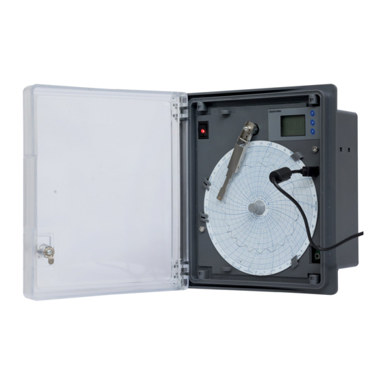
Summary of Contents for G-Tek 27 Series
- Page 1 OPERATING MANUAL CR-2010 BBR Circular Chart Recorder CR-2010 BBR Model No.: 27xx... G-Tek Corporation Pvt. Ltd. 3, mahavir estate, karelibaug vadodara-390 018 tel.: +91-265-2461912 email: info@gtek-india.com url: www.gtek-india.com...
-
Page 2: Table Of Contents
Contents LIST OF TABLES .............................. 1 LIST OF FIGURES ............................1 LIST OF ABBREVIATIONS ..........................2 SAFETY AND THE ENVIRONMENT ........................3 ............................. 3 BOUT THIS DOCUMENT ..............................3 NSURE AFETY .......................... 3 ROTECTING THE ENVIRONMENT SPECIFICATIONS ............................4 ................................4 ................................ -
Page 3: List Of Tables
IST OF TABLES Table 1 Technical data ..........................5 Table 2 Chart type of Chart Recorder ......................7 Table 3 Overall Mechanical Dimensions ..................... 11 Table 4 Connection Notations ........................14 Table 5 Troubleshooting Guide ........................23 Table 6 Order code............................25 IST OF FIGURES Figure 1 Front View of Recorder ........................ -
Page 4: List Of Abbreviations
IST OF ABBREVIATIONS Abbreviation Description Set RTC Date Month Year Hour Minute Save No Battery ON Battery Battery Low Offset Menu Mechanical Calibration Menu Pen zero scale position Pen full scale position Calibration in progress Zero scale position test Full scale position test Page No. -
Page 5: Safety And The Environment
AFETY AND THE ENVIRONMENT 4.1 A BOUT THIS DOCUMENT ➢ This instruction manual is an essential component of the product. ➢ Please read this documentation through carefully and attention to the safety instructions and warning notices to prevent injuries and damage to the product. ➢... -
Page 6: Specifications
PECIFICATIONS 5.1 U ➢ This recorder is specially tailored to monitor the blood bank refrigerator temperature data. ➢ This recorder also has an input for door open switch. The door opening and closing is very frequent during the removal of the stored blood, it is easy to monitor how often and for how much time the door was left open with this recorder. -
Page 7: Technical Data
5.3 T ECHNICAL Table 1 Technical data Model No CR2010 Series; BBR Chart Recorder Product Code* 27x03 Recording System No. of Pens 1 – Suitable for marking on Pressure Sensitive Paper Pen Marking Continuous Pen Response Time <5Sec (Full Scale) Pen Resolution Stepper Motor Controlled better than 0.1% FSD Overshoot... - Page 8 Communication Type USB 2.0 PC Application BBR-Chart to download data; Configure recorder and generate report. Protection Input Impedance > 20 MΩ CMRR >100 dB@ 50, 60 Hz at 3 Sample per Second NMRR >50 dB@ 50, 60 Hz at 3 Samples per Second Maximum Common Mode Voltage 5 V AC Isolation Channel –...
-
Page 9: Table 2 Chart Type Of Chart Recorder
**Refer to the back panel of recorder for exact rating. Table 2 Chart type of Chart Recorder Sr. No. Range** Speed Size Part No. Part Description 0 to +100 6” 304001 D60100 0 to +150 6” 304002 D60150 0 to +200 6”... -
Page 10: Unpacking And Inspection Of Recorder
NPACKING AND NSPECTION OF ECORDER ➢ If the outer box shows sign of damage, it should be opened immediately, and the recorder be examined. ➢ If there is evidence of damage, the instrument should not be operated, and the local representative contacted for instructions. -
Page 11: Figure 2 Back View Of Recorder
RTD connection Door switch connection 12VDC battery connection LNE (mains) connection Figure 2 Back view of Recorder Page No. 9... -
Page 12: Installation
6.1 I NSTALLATION Figure-3 A Figure-3 B Figure 3 Environmental Conditions Environmental Conditions: Recorder should be used with proper environmental conditions for better operation. The environmental conditions are shown in Figure 3. Attention Select a location away from strong electrical and magnetic field. If this is not possible, particularly in application where mobile communication device is expected to be used, screened cables within earthed (grounded) metal contact must be used as shown in above figure 3B. -
Page 13: Overall Mechanical Dimensions
6.2 O VERALL ECHANICAL IMENSIONS Figure 4 Overall Mechanical Dimensions Table 3 Overall Mechanical Dimensions Overall Dimensions(approx.) Dimensions L x W x D (mm) 232 x 205 x 117 Panel Cutout L X W (mm) 198 x 169 Bezel L x W (mm) 232 x 205 Page No. -
Page 14: Figure 5 Panel Mounting
The panel mounting of recorder is shown in figure 5. Figure 5 Panel Mounting Page No. 12... -
Page 15: Electrical Installation
LECTRICAL NSTALLATION 7.1 W IRING DIAGRAM FOR ECORDER ➢ Refer the figure 6, to connect AC mains,12V DC Input, door switch input and sensor to the recorder. connection Door switch connection 12VDC battery connection LNE (Mains) connection Figure 6 Back panel view with notation Page No. -
Page 16: Table 4 Connection Notations
Table 4 Connection Notations Code Connector Name Pin Number of connectors Sensor input RTD (PT-100) 3-Wire Door Switch Door switch input Battery 12 V DC Battery AC supply 85 – 264 V AC supply Line (L) Neutral(N) Earth (E) 47 – 63 Hz ➢... -
Page 17: Fitting The Chart
7.2 F ITTING THE HART Figure 7 Chart Fitting To replace the chart, follow the steps: 1. Open the door of the recorder. 2. Park the pen on full scale position. 3. Unscrew the chart knob as shown in figure 7. 4. -
Page 18: Operation
PERATION 8.1 F RONT ANEL OF ECORDER After the proper wiring is done, pen and chart fitted properly, Power ON the recorder. The pen will move towards the center of the chart. After it reaches the center of the chart, it stops there. After a while pen will move to the position on the charts as per the parameter value. -
Page 19: Set Rtc Menu
MENU 9.1 S RTC M EQUENCE ➢ In normal condition the display is off, by pressing function key user can enter to the Set RTC (Sr) menu as shown in figure 9. ➢ Once you enter in the Sr menu, you must set the RTC otherwise the default value will be set for DD, MM, YY, HR &... -
Page 20: View Current Time & Battery Status Indication
Note: Pressing both (UP & DOWN) keys at a time works as enter key. Ensure that the DD, MM, YY, HR and MN values are set properly. Keys: To increment the value. To decrement the value. To save the value & go to next step. &... -
Page 21: Figure 10 View Current Time
Display for 3sec. Display in normal condition is off. Display for 3sec. Display for 3sec. Display for 3sec. Display for 3sec. Display for 3sec. Figure 10 View current time ➢ “Display shows only one status out of these four as per the connection to the device”. ➢... -
Page 22: Offset Menu
FFSET ➢ If the user wants to add positive/negative offset to the reading, it can be applied by accessing the Offset menu. ➢ This menu involves application of an offset in current reading, through the front panel keyboard. User can give an offset in current reading by the sequence shown in figure 12. ➢... -
Page 23: Calibration Menu
ALIBRATION 11.1 M ECHANICAL CALIBRATION ➢ This involves setting of Pen zero and Pen full scale on chart, through the front panel keyboard. User can calibrate the Recorder by following the sequence shown in figure 13. ➢ The time-out for mechanical calibration for display is 10 minutes, after that the display will be off. - Page 24 Note: If the error is large, you may need to carry out same exercise twice or thrice to set the value properly. “cal” Status is blinking during the calibration process on display. Keys: Pen is moved away from the center of the chart Pen is moved towards the center of the chart Page No.
-
Page 25: Troubleshooting Guide
Check if Chart knob is tightened properly. • If chart does not move still, then contact factory. • Calibration settings cannot be Contact factory. performed. NOTE: if you face any other problem, please contact G-Tek Corporation Pvt. Ltd. Page No. 23... -
Page 26: Standard Accessories
TANDARD CCESSORIES Charts Pack of 30 Panel Mounting Clamps: - 2 numbers Standard Accessories Optional Accessories Figure 14 Accessories Page No. 24... -
Page 27: Order Code
RDER The Order code for the chart recorder is as below: Table 6 Order code P= Pen, C=Chart PS = Power Width Thermal- Supply CT - PI = PC Pen, D= TS - RE = Relay Chart R=Range CS=Chart Speed S=Sensor Type Interface Recorder...
Need help?
Do you have a question about the 27 Series and is the answer not in the manual?
Questions and answers