
Subscribe to Our Youtube Channel
Related Manuals for LSLIDAR CH128X1

Summary of Contents for LSLIDAR CH128X1
- Page 1 CH128X1 User Manual V1.0.3 2022.12 LeiShen Intelligent System Co., LTD http://www.lslidar.com/...
- Page 2 Safety Instruction Before using the product, please read and follow the instructions of this manual carefully, and refer to relevant national and international safety regulations. ∆Attention Please do not disassemble or modify the lidar privately. If you need special instructions, please consult our technical support staff. ∆Laser Safety Level The laser safety of this product meets the following standards: ●...
- Page 3 the power supply requirements, or supply power in a humid environment may cause abnormal operation, fire, personal injury, product damage, or other property loss. Light Interference Some precise optical equipment may be interfered with by the laser emitted by this product, please pay attention when using it. Vibration Please avoid product damage caused by strong vibration.
-
Page 4: Table Of Contents
TABLE OF CONTENTS 1. PRODUCT PROFILE .......................... 1 1.1 O ............................1 VERVIEW 1.2 M ............................1 ECHANISM 1.3 S ............................. 1 PECIFICATION 1.4 D ............................2 IMENSIONS 2. ELECTRICAL INTERFACE ......................... 4 2.1 P ............................ 4 OWER UPPLY 2.2 E ........................ - Page 5 5.3.2 Configuration Package Example ..................30 6. TIME SYNCHRONIZATION ......................30 6.1 GPS S ........................31 YNCHRONIZATION 6.2 E ......................32 XTERNAL YNCHRONIZATION PTP S ......................... 33 YNCHRONIZATION 6.4 L ........................33 IDAR NTERNAL IMING 7. ANGLE AND COORDINATE CALCULATION................34 7.1 V ..........................
-
Page 6: Product Profile
1.2 Mechanism The CH128X1 Hybrid Solid-State Lidar adopts the Time of Flight method. The Lidar starts timing (t ) when the laser pulses are sent out. And when the laser... -
Page 7: Dimensions
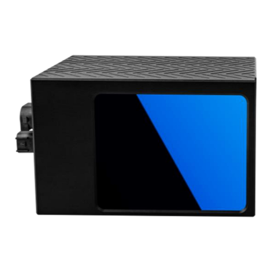
1 kg 1.4 Dimensions There are 4 mounting holes and 2 positioning holes at the bottom of CH128X1 Lidar. Four M5*10 (hexagon socket head cap screws) mechanical screws with spring washers and flat washers are needed for locking and fixing the Lidar. See the outline dimension drawing shown in Figure 1.2. - Page 8 The CH128X1 Lidar utilizes mirror rotation and special optical design to scan 120° horizontally, with a dense light distribution of 128 lines. Figure 1.3 shows the appearance of the CH128X1 Lidar while Figure 1.4 shows the optical center position, which is also the coordinate origin of the host computer display software.
-
Page 9: Electrical Interface
2. Electrical Interface 2.1 Power Supply The power input range of the CH128X1 Lidar is 9V~36VDC. If other DC power supply is adopted, the recommended output voltage of the power supply is 12VDC, 19VDC or 24VDC. Please note that DC 9V and 36V are short-term power supply in extreme environment, which cannot be used as working voltage. -
Page 10: Electrical Interface
2.2 Electrical Interface The cables from the side of the CH128X1 lidar base are a 6-pin power supply cable and a 2-pin automotive ethernet cable. The cables are as shown in the figures below. - Page 11 Figure 2.2 The 6-PIN Power Supply Cable ② Table 2.2 Wiring Definition of the 6-PIN Power Supply Cable ② Definition (for lidar Definition (for lidar Color Description Description with CAN protocol) with GPS time service) GPS Inputting White GPS_PPS PPS Signal Power+ Power+ Black...
- Page 12 Lidar. Please note that the interface box is not a necessary accessory for Lidar operation. The interface box of the CH128X1 Lidar includes: an automotive ethernet port, an automotive power port, a Φ2.1 mm DC socket, an indicator light, a RJ45 network port and a 6-PIN GPS port, as shown in Figure 2.4.
-
Page 13: Get Ready
GPS module and power supply though the interface box as shown in Figure 3.1. Figure 3.1 Connecting the Lidar 3.2 Software Preparation The LeiShen CH128X1 Lidar can be operated under both Windows operating system and Linux operating system. Software needed is as follows: Wireshark: to capture the ARP (Address Resolution Protocol) packets. -
Page 14: Usage Guide
higher achieves the best effect, otherwise the display of the point cloud may be affected. And the computer graphics card must support OpenGL 2 or higher graphics acceleration to display the point cloud normally. ⚫ Supplemental Software To use the Windows Client, the installation of the WinPcap third-party library is necessary. -
Page 15: Windows Client Interface
The Lidar IP (local IP) and the computer IP (destination IP) cannot be set to the same, otherwise the Lidar will not work normally. In the multicast mode, no two destination ports should be set to the same port number. The lidar IP range are forbidden to be set to... - Page 16 table area, etc. Figure 4.2 Initial Interface Note: In the point cloud display area (right side), with 20 circles and 40*40 grids, the radius of each two adjacent circles differs by 10 m. The difference between each two grids (horizontal or longitudinal) is 10 m. And the radius of the outermost circle is 200 m.
- Page 17 Show/hide measurement grid Mark the selected points in the point cloud image Pause point cloud image and data generating Select point clouds from different angles Clear screen Show/hide coordinate Show/hide the column on the left Three-view option: set the observation angle from top, front, and left.
-
Page 18: Operation Procedure
information. According to the DIFOP status packet sent out regularly by the lidar, the current status information is displayed, including GPS position information, satellite time information, motor speed, current lidar IP, and current lidar port number. Vertical Angle column represents the vertical angle of the corresponding channel data and Channel Select laser channel column represents the data sequence number... -
Page 19: Point Cloud Data Parsing
Figure 4.3 Real-Time Lidar Point Cloud Display 4.1.4 Point Cloud Data Parsing If you need to parse Lidar data, please follow the steps below: Step 1. Parse the data package to obtain the relative horizontal angle, ranging information, intensity data and microsecond timestamp information of each laser; Step 2. - Page 20 2) At the same time, since Qt is adopted in the low-level software development, please create English paths when naming files and path folders. 3) Since the port number of the LeiShen CH128X1 Lidar can be modified through user configuration, and the Lidar sends data to the host computer through the preset destination IP and port.
- Page 21 Figure 4.5 Network Connections Step 3. In the TCP/IPv4 property settings, set the IP address to the Lidar's destination IP (The default destination IP of the Lidar is 192.168.1.102), and the subnet mask is set to 255.255.255.0. Figure 4.6 IP Address and Subnet Mask Setting 4) Since the LeiShen Lidar display software needs to obtain a large number of...
- Page 22 data packets through the network in a short time, it may be considered as a malicious program by the network firewall and be prohibited. Therefore, there may be situations in which the data packet has been sent to the computer by the Wireshark software, but the point cloud display software cannot display it.
-
Page 23: Ros Driver Operation Under Linux Os
and select “NVIDIA Control Panel”. Step 2. Select the “Manage 3D Settings” in the NVIDIA Control Panel interface. Step 3. Click the “Program Settings” button in the Manage 3D Settings interface. Step 4. Click the “Add” button on the Manage 3D Settings interface. Step 5. -
Page 24: Software Operation Example
connected normally. If the ping is successful, then the data is received, otherwise check the hardware connection. Step 5. Use “sudo tcpdump -n -i eth0” (here eth0 is the name of the wired network device, see the device name of ifconfig wired connection display for details) to view the data packets sent by the Lidar (as shown in the figure, there are 1206-byte data packets sent by the Lidar to the destination, which means that the Lidar data is sent normally). -
Page 25: Communication Protocol
Note 1): If the Lidar destination port and motor speed are modified, please open “lslidar_ch.launch” to modify the configuration accordingly. The default data packet port is 2368, device packet port is 2369, IP address is 192.168.1.200. Note 2): If timeout appears, it means that the driver has no data reception. Please check the hardware connection. -
Page 26: Format
(including 1 bytes of UTC time of second, 4 bytes of Timestamp and 2 bytes of Factory). 5.1.1 Format The CH128X1 Lidar supports single echo mode which measures the most recent echo value and dual echo mode which measures the most recent and second recent echo values. -
Page 27: Data Package Parameter Description
Each MSOP data packet contains 1206 bytes of data. Each packet of data contains 109 points, that is, 109*11=1199 bytes, and the frame tail is 7 bytes (including 1 byte of UTC time of second, 4 bytes of Timestamp and 2 bytes of Factory). - Page 28 Length (0x04BE, represent 1214 UDP Length & bytes) Sum Check Sum Check Subframe (Single Echo Mode) The subframe is the effective data area of the data packet, which contains a total of 1197 bytes, including 171 points, that is, 171*7=1197 bytes. Take the first measure point as an example: Byte 1 represents the line number, whose value range from 0 to 127, a total of 128 lines.
- Page 29 Byte 1 represents the line number, whose value range from 0 to 127, a total of 128 lines. The 128 lines respectively corresponds to the lowermost ray to the uppermost ray in the entire vertical field of view. For example, line No. 0 represents a vertical angle of -18°, line No.
- Page 30 Length (byte) Function UTC time Hour, minute and second of the UTC time Timestamp Timestamp (μs) Vendor 0x80 represents the CH128X1 Lidar Information Factory Echo 0x1 represents single echo Lidar Information 0x2 represents dual echo Lidar Additional Information (dual echo mode): 7 bytes...
-
Page 31: Difop Protocol
Timestamp Timestamp (μs) Vendor 0x80 represents the CH128X1 Lidar Information Factory Echo 0x1 represents single echo Lidar Information 0x2 represents dual echo Lidar 1) When there is a GPS device inputting PPS signal to the Lidar, the timestamp is generated according to the PPS time as the cycle time, and the range of the timestamp is 0-999999 (μs);... -
Page 32: Ucwp Protocol
Length (0x04BE, represents 1214 UDP Length bytes) & Sum Check Sum Check Payload: 1206 bytes Length Name Information Offset (byte) Header Device Package Identification Header Motor Speed Ethernet Configuration Lidar Rotation / Stationary Data Device Flow Packet Interval GPS Time Latitude and Longitude Tail Frame Tail... -
Page 33: Configuration Parameters And Status Description
Version, Header Length, Differentiated Services, Field, Total Length, Identification, Flags, Internet Fragment Offset, Time to Live, Protocol Protocol, Header, Checksum, Source IP Address, Destination IP Address Lidar Port (0x0941, represent 2369) UDP Port Computer Port (0x0940, represent Number 2368) Length (0x04BE, represent 1214 UDP Length bytes) &... - Page 34 the UDP data port number and port2 is the UDP device port number. Ethernet Configuration(22 bytes) Byte1 Byte2 Byte3 Byte4 Byte5 Byte6 Byte7 Byte8 Function IP_SRC IP_DEST Byte9 Byte10 Byte11 Byte12 Byte13 Byte14 Byte15 Byte16 Function MAC_ADDR (Read Only) Data Port: Port1 Byte17 Byte18 Byte19 Byte20 Byte21 Byte22 Function...
-
Page 35: Configuration Package Example
Function Longitude Byte17 Byte18 Byte19 Byte20 Byte21 Byte22 Function The latitude and longitude are output in the form of ASCII code. 5.3.2 Configuration Package Example If you want to reset the Lidar IP as 192.168.1.105, computer IP as 192.168.1.225, data port number as 6688, device port number as 8899, motor speed as 1200 rmp, according to the definition of the UCWP Packet and each register, it can be reconfigured as follows: Table 5.4 Configuration Package Example... -
Page 36: Gps Synchronization
There are two types of CH128X1 Lidar GPS_REC interface level protocols, namely TTL level standard and RS232 level standard; the GPS_REC interface specification on the power box is SH1.0-4P female socket. The two protocols... -
Page 37: External Synchronization
point cloud can be matched with the pitch, roll, yaw, latitude, longitude and height of the GPS/inertial measurement system. The default serial configuration baud rate of the GPS data output received by the Lidar is 9600, 8N1. The PPS high pulse width is required to be more than 1ms. -
Page 38: Gptp Synchronization
more than 1 ms. 6.3 gPTP Synchronization Generalized Precise Time Protocol (gPTP) is derived from Precise Time Protocol (PTP) and is used to synchronize the time of individual devices within a local area network with high precision. This series of lidar supports gPTP timing synchronization. Before synchronizing the lidar via gPTP, the time source needs to be set to “PTP”... -
Page 39: Angle And Coordinate Calculation
7. Angle and Coordinate Calculation 7.1 Vertical Angle Take single echo mode as an example: The vertical angle is obtained from the data packet, whose effective data area contains a total of 1197 bytes, including 171 points, that is, 171*7=1197 bytes. Take the first measure point as an example: Byte 1 represents the line number, whose value range from 0 to 127, a total of 128 lines. -
Page 40: Distance Value And Intensity
Endian mode. The unit is 0.01 degrees. For example, 0x11AD=4525, that is 45.25°. 7.3 Distance Value and Intensity Byte 4, Byte 5, and Byte 6 represent the the first echo distance value. Their data are stored in Big-Endian mode. The two high bytes are the integer part, whose unit is “cm”;... -
Page 41: Accurate Time Calculation
Lidar. The timestamp and UTC time come from the same synchronization source, such as a GPS. The laser emission interval of the CH128X1 Lidar is about 0.868μs, and the measurement interval of adjacent points is 0.868 μs. 8.1 Single Echo Mode In the single echo mode, a data packet has a total of 171 measurement data. -
Page 42: Dual Echo Mode
Each data packet block of the CH128X1 Lidar contains 171 measurement data. Therefore, the end time interval of each data packet (single echo mode) is 148.428 μs. Assuming that the absolute time of the data packet end is T Packet_end... - Page 43 Revision History Issued/Revised Rev. Release Date Revised Content V1.0.0 2022-02-24 Initial Version LS1286 gPTP time synchronization V1.0.1 2022-07-20 added; 6-pin cable LS1286 definition modified New power cable and wire V1.0.2 2022-11-09 definition added; note of LS1286 lidar IP setting added 6.3 gPTP Synchronization V1.0.3 2022-12-22...
- Page 44 60 Rue Saint Antoine 75004 Paris, France TEL: 0033-(0)749044832 Eric Chen Sales Email: sales@lslidar.com After-Sales Mailbox: support@lslidar.com Company Website: www.lslidar.com *This product information is subject to change without notice. Copyright © 2022 LeiShen Intelligent System Co., Ltd. All rights reserved.
Need help?
Do you have a question about the CH128X1 and is the answer not in the manual?
Questions and answers