Table of Contents
Advertisement
Unpacking
Thank you for buying the MSI
®
Z370I GAMING PRO CARBON AC
motherboard. Check
to make sure your motherboard box contains the following items. If something is
missing, contact your dealer as soon as possible.
Drivers & Utilities
Motherboard User
Disc
Guide
Motherboard
I/O Shield
SATA Cable x2
RGB LED Extension
Cable 80cm x1
SATA Cable Labels
CORSAIR HD RGB LED
Cable 50cm x1*
Antenna x2
* Only for connecting the Corsair HD Series, HD120 RGB LED Case Fan.
1
Unpacking
Advertisement
Table of Contents
Troubleshooting

Related Manuals for MSI Z370I GAMING PRO CARBON AC


Summary of Contents for MSI Z370I GAMING PRO CARBON AC
-
Page 1: Unpacking
Unpacking Thank you for buying the MSI ® Z370I GAMING PRO CARBON AC motherboard. Check to make sure your motherboard box contains the following items. If something is missing, contact your dealer as soon as possible. Drivers & Utilities Motherboard User... -
Page 2: Safety Information
Safety Information y The components included in this package are prone to damage from electrostatic discharge (ESD). Please adhere to the following instructions to ensure successful computer assembly. y Ensure that all components are securely connected. Loose connections may cause the computer to not recognize a component or fail to start. -
Page 3: Quick Start
Quick Start Preparing Tools and Components ® Intel LGA 1151 CPU CPU Fan Thermal Paste DDR4 Memory Power Supply Unit Chassis SATA Hard Disk Drive Graphics Card SATA DVD Drive A Package of Screws Phillips Screwdriver Quick Start... -
Page 4: Installing A Processor
Installing a Processor https://youtu.be/4ce91YC3Oww Quick Start... -
Page 5: Installing Ddr4 Memory
Installing DDR4 memory http://youtu.be/T03aDrJPyQs Quick Start... -
Page 6: Connecting The Front Panel Header
Connecting the Front Panel Header http://youtu.be/DPELIdVNZUI HDD LED + Power LED + HDD LED - Power LED - Reset Switch Power Switch Reset Switch Power Switch JFP1 Reserved No Pin JFP1 HDD LED - HDD LED HDD LED + POWER LED - POWER LED POWER LED + Quick Start... -
Page 7: Installing The Motherboard
Installing the Motherboard Quick Start... -
Page 8: Installing Sata Drives
Installing SATA Drives http://youtu.be/RZsMpqxythc Quick Start... -
Page 9: Installing A Graphics Card
Installing a Graphics Card http://youtu.be/mG0GZpr9w_A Quick Start... -
Page 10: Connecting Peripheral Devices
Connecting Peripheral Devices Quick Start... -
Page 11: Connecting The Power Connectors
Connecting the Power Connectors http://youtu.be/gkDYyR_83I4 ATX_PWR1 CPU_PWR1 Quick Start... -
Page 12: Power On
Power On Quick Start... -
Page 13: Table Of Contents
Contents Unpacking ......................1 Safety Information ....................2 Quick Start ......................3 Preparing Tools and Components ................3 Installing a Processor ..................... 4 Installing DDR4 memory ..................5 Connecting the Front Panel Header ............... 6 Installing the Motherboard ..................7 Installing SATA Drives..................... - Page 14 LIVE UPDATE 6 ...................... 63 COMMAND CENTER ..................... 65 GAMING APP ......................69 X-BOOST ....................... 74 MYSTICLIGHT ......................76 MSI SMART TOOL ....................78 RAMDISK....................... 80 GAMING LAN MANAGER ..................81 DRAGON EYE ......................83 Nahimic 2 ......................84 SteelSeries Engine 3 .................... 88 ®...
- Page 15 RAID Configuration ....................96 Using Intel ® Rapid Storage Technology Option ROM ........... 96 Degraded RAID Array ................... 99 ® Intel Optane™ Memory Configuration ............101 System Requirements ..................101 Installing the Intel ® Optane™ memory .............. 101 Removing the Intel ®...
-
Page 16: Specifications
Supports non-ECC, un-buffered memory y Supports Intel ® Extreme Memory Profile (XMP) * Please refer www.msi.com for more information on compatible memory. y 1x PCIe 3.0 x16 slot Expansion Slots y 1x HDMI™ port, supports a maximum resolution of... - Page 17 Continued from previous page ® Intel Dual Band Wireless-AC 8265 module y The Wireless module is pre-install in the M2_2 (M.2 Key E) slot. Wirsless LAN & y Supports Wi-Fi 802.11 a/b/g/n/ac, dual band (2.4GHz, Bluetooth ® 5GHz) up to 867 Mbps speed. y Supports Dual Mode Bluetooth ®...
- Page 18 Continued from previous page y 1x 24-pin ATX main power connector y 1x 8-pin ATX 12V power connector y 4x SATA 6Gb/s connectors y 1x USB 3.1 Gen1 connector (supports additional 2 USB 3.1 Gen1 ports) y 1x USB 2.0 connector (supports additional 2 USB 2.0 ports) y 1x 4-pin CPU fan connector y 1x 4-pin system fan connector Internal Connectors...
- Page 19 Continued from previous page y Drivers y APP MANAGER y SUPER CHARGER y COMMAND CENTER y LIVE UPDATE 6 y MSI SMART TOOL y RAMDISK y DPC LATENCY TUNER y FAST BOOT y X-BOOST y DRAGON EYE y GAMING APP...
- Page 20 Continued from previous page y Storage ƒ Turbo M.2 y Fan ƒ Smart Fan Control y LED ƒ Mystic Light ƒ Mystic Light Extension (RGB) ƒ Corsair Extension ƒ Mystic light SYNC ƒ EZ DEBUG LED y Protection ƒ DDR4 Steel Armor ƒ...
-
Page 21: Block Diagram
Block Diagram HDMI 2 Channel DDR4 Memory PCI-E Bus M.2 (Key-E) DMI 3.0 Wifi-module 1 x M.2 Intel I219-V 4 x SATA 6Gb/s Z370 4 x USB 3.1 Gen1 PCI-E Bus 4 x USB 2.0 ASMEDIA LPC Bus ASM3142 2 x USB 3.1 Gen2 NV5565 Realtek Super I/O... -
Page 22: Rear I/O Panel
Rear I/O Panel Wi-Fi Antenna connectors Audio Ports PS/2 USB 3.1 Gen2 DisplayPort Clear CMOS button USB 3.1 Gen1 USB 2.0 USB 3.1 Gen2 Optical S/PDIF-Out Type-C y Clear CMOS button - Power off your computer. Press and hold the Clear CMOS button for about 5-10 seconds to reset BIOS to default values. -
Page 23: Realtek Hd Audio Manager
Realtek HD Audio Manager After installing the Realtek HD Audio driver, the Realtek HD Audio Manager icon will appear in the system tray. Double click on the icon to launch. Device Selection Advanced Settings Jack Status Application Enhancement Connector Main Volume Settings Profiles y Device Selection - allows you to select a audio output source to change the related... - Page 24 Audio jacks to headphone and microphone diagram Audio jacks to stereo speakers diagram AUDIO INPUT Audio jacks to 7.1-channel speakers diagram AUDIO INPUT Rear Front Side Center/ Subwoofer Rear I/O Panel...
-
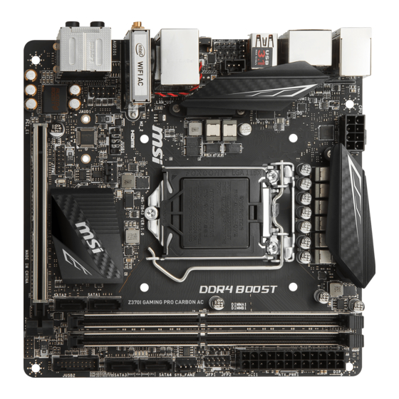
Page 25: Overview Of Components
Overview of Components Top View DIMMA1 JUSB1 CPU Socket DIMMB1 SATA1 CPU_PWR1 ATX_PWR1 JCORSAIR1 JCI1 JRGB1 JFP1 JFP2 JBAT1 SYS_FAN1 SATA4 M2_2 SATA3 JAUD1 JUSB2 SATA2 JTPM1 PCI_E1 CPU_FAN1 Bottom View M2_1 Overview of Components... - Page 26 Component Contents Port Name Port Type Page CPU_FAN1, SYS_FAN1 Fan Connectors CPU_PWR1, ATX_PWR1 Power Connectors CPU Socket LGA1151 CPU Socket DIMMA1, DIMMB1 DIMM Slots JAUD1 Front Audio Connector JBAT1 Clear CMOS (Reset BIOS) Jumper JCI1 Chassis Intrusion Connector JFP1, JFP2 Front Panel Connectors JRGB1, JCORSAIR1 RGB LED Connectors...
-
Page 27: M2_1: M.2 Slot (Key M)
M2_1: M.2 Slot (Key M) Important Before you install the motherboard into the case, make sure your M.2 module has been installed properly. Intel ® RST only supports PCIe M.2 SSD with UEFI ROM. Intel ® Optane™ Memory Ready for all M.2 slot. Video Demonstration Watch the video to learn how to use M.2 Shield. -
Page 28: Cpu Socket
Always unplug the power cord from the power outlet before installing or removing the CPU. Please retain the CPU protective cap after installing the processor. MSI will deal with Return Merchandise Authorization (RMA) requests if only the motherboard comes with the protective cap on the CPU socket. -
Page 29: Dimm Slots
DIMM Slots DIMMA1 DIMMB1 Channel A Channel B Important Always insert memory modules in the DIMMA1 slot first. Due to chipset resource usage, the available capacity of memory will be a little less than the amount of installed. Based on Intel CPU specification, the Memory DIMM voltage below 1.35V is suggested to protect the CPU. -
Page 30: Pci_E1: Pcie Expansion Slot
PCI_E1: PCIe Expansion Slot Important If you install a large and heavy graphics card, you need to use a tool such as MSI Gaming Series Graphics Card Bolster to support its weight to prevent deformation of the slot. When adding or removing expansion cards, always turn off the power supply and unplug the power supply power cable from the power outlet. -
Page 31: Cpu_Pwr1, Atx_Pwr1: Power Connectors
CPU_PWR1, ATX_PWR1: Power Connectors These connectors allow you to connect an ATX power supply. CPU_PWR1 Ground +12V Ground +12V Ground +12V Ground +12V +3.3V +3.3V +3.3V -12V Ground Ground PS-ON# Ground Ground Ground ATX_PWR1 Ground Ground PWR OK 5VSB +12V +12V +3.3V Ground... -
Page 32: Jusb1: Usb 2.0 Connector
JUSB1: USB 2.0 Connector This connector allows you to connect USB 2.0 ports on the front panel. USB0- USB1- USB0+ USB1+ Ground Ground No Pin Important Note that the VCC and Ground pins must be connected correctly to avoid possible damage. -
Page 33: Cpu_Fan1, Sys_Fan1: Fan Connectors
CPU_FAN1, SYS_FAN1: Fan Connectors Fan connectors can be classified as PWM (Pulse Width Modulation) Mode or DC Mode. PWM Mode fan connectors provide constant 12V output and adjust fan speed with speed control signal. DC Mode fan connectors control fan speed by changing voltage. When you plug a 3-pin (Non-PWM) fan to a fan connector in PWM mode, the fan speed will always maintain at 100%, which might create a lot of noise. -
Page 34: Jaud1: Front Audio Connector
JAUD1: Front Audio Connector This connector allows you to connect audio jacks on the front panel. MIC L Ground MIC R Head Phone R MIC Detection SENSE_SEND No Pin Head Phone L Head Phone Detection JCI1: Chassis Intrusion Connector This connector allows you to connect the chassis intrusion switch cable. Normal Trigger the chassis intrusion event... -
Page 35: Jtpm1: Tpm Module Connector
JTPM1: TPM Module Connector This connector is for TPM (Trusted Platform Module). Please refer to the TPM security platform manual for more details and usages. LPC Clock 3V Standby power LPC Reset 3.3V Power LPC address & data pin0 Serial IRQ LPC address &... -
Page 36: Jrgb1, Jcorsair1: Rgb Led Connectors
The JRGB1 connector allows you to connect the 5050 RGB LED strips 12V. The JCORSAIR1 connector can be used to connect the CORSAIR Individually Addressable RGB LED strips 5V or CORSAIR RGB LED fans, and control the RGB effects with MSI s software. -
Page 37: Onboard Leds
Onboard LEDs EZ Debug LEDs These LEDs indicate the debug status of the motherboard. CPU - indicates CPU is not detected or fail. DRAM - indicates DRAM is not detected or fail. VGA - indicates GPU is not detected or fail. BOOT - indicates the booting device is not detected or fail. -
Page 38: Bios Setup
Press Delete key, when the Press DEL key to enter Setup Menu, F11 to enter Boot Menu message appears on the screen during the boot process. y Use MSI FAST BOOT application. Click on GO2BIOS button and choose OK. The system will reboot and enter BIOS setup directly. -
Page 39: Resetting Bios
Updating BIOS Updating BIOS with M-FLASH Before updating: Please download the latest BIOS file that matches your motherboard model from MSI website. And then save the BIOS file into the USB flash drive. Updating BIOS: 1. Press Del key to enter the BIOS Setup during POST. -
Page 40: Ez Mode
EZ Mode At EZ mode, it provides the basic system information and allows you to configure the basic setting. To configure the advanced BIOS settings, please enter the Advanced Mode by pressing the Setup Mode switch or F7 function key. XMP switch Setup Mode switch Screenshot... - Page 41 y Information display - click on the CPU, Memory, Storage, Fan Info and Help buttons on left side to display related information. y Function buttons - enable or disable the LAN Option ROM, M.2/Optane Genie, HD audio controller, AHCI, RAID, CPU Fan Fail Warning Control and BIOS Log Review by clicking on their respective button.
-
Page 42: Advanced Mode
Advanced Mode Press Setup Mode switch or F7 function key can switch between EZ Mode and Advanced Mode in BIOS setup. XMP switch Setup Mode switch Screenshot Search Language System information GAME BOOST switch Boot device priority bar BIOS menu BIOS menu selection selection... -
Page 43: Settings
SETTINGS System Status f System Date Sets the system date. Use tab key to switch between date elements. The format is <day> <month> <date> <year>. <day> Day of the week, from Sun to Sat, determined by BIOS. Read-only. <month> The month from Jan. through Dec. <date>... - Page 44 fPEG X - Max Link Speed [Auto] Sets PCI Express protocol of PCIe x16 slots for matching different installed devices. [Auto] This item will be configured automatically by BIOS. [Gen1] Enables PCIe Gen1 support only. [Gen2] Enables PCIe Gen2 support only. [Gen3] Enables PCIe Gen3 support only.
- Page 45 fIpv6 PXE Support [Enabled] When Enabled, the system UEFI network stack will support Ipv6 protocol. This item will appear when Network Stack is enabled. [Enabled] Enables the Ipv6 PXE boot support. [Disabled] Disables the Ipv6 PXE boot support. fSATA Mode [AHCI Mode] Sets the operation mode of the onboard SATA controller.
- Page 46 Disables this function. fMSI Fast Boot [Disabled] MSI Fast Boot is the fastest way to boot the system. It will disable more devices to speed up system boot time which is faster than the boot time of Fast Boot. [Enabled] Enables the MSI Fast Boot function to speed up booting time.
- Page 47 Important When MSI Fast Boot is enabled, you can use MSI FAST BOOT application to enter BIOS setup if needed. Please refer Entering BIOS Setup section for details. fFast Boot [Enabled/ windows 10, Disabled/ windows7] Enables or disables the fast boot feature for Windows 10. This item will only be available when MSI Fast Boot is disabled.
-
Page 48: Boot
fDate (of month) Alarm/ Time (hh:mm:ss) Alarm Sets RTC alarm date/ Time. If Resume By RTC Alarm is set to [Enabled], the system will automatically resume (boot up) on a specified date/hour/minute/second in these fields (using the + and - keys to select the date & time settings). fResume By PCI-E Device [Disabled] Enables or disables the wake up function of installed PCI-E expansion cards, integrated LAN controllers or USB devices which are supported by third party... -
Page 49: Security
f GO2BIOS [Disabled] Allows system to enter BIOS setup directly by pressing the Power button for 4 sec pon bootup. [Enabled] The system boots straight to the BIOS setup by long pressing the power button about 4 seconds when the system is off. [Disabled] Disables this function. - Page 50 f Password Clear [Enabled] Enables or disables the clear CMOS behavior to clear a set password. [Enabled] The password will be erased after clear CMOS. [Disabled] The password will always be kept. Important When selecting the Administrator / User Password items, a password box will appear on the screen.
-
Page 51: Save & Exit
Save & Exit f Discard Changes and Exit Exit BIOS setup without saving any change. f Save Changes and Reboot Save all changes and reboot the system. f Save Changes Save current changes. f Discard Changes Discard all changes and restore to the previous values. f Restore Defaults Restore or load all default values. - Page 52 Important Overclocking your PC manually is only recommended for advanced users. Overclocking is not guaranteed, and if done improperly, it could void your warranty or severely damage your hardware. If you are unfamiliar with overclocking, we advise you to use GAME BOOST function for easy overclocking.
- Page 53 fEIST [Enabled]* ® Enables or disables the Enhanced Intel SpeedStep Technology. [Enabled] Enables the EIST to adjust CPU voltage and core frequency dynamically. It can decrease average power consumption and average heat production. [Disabled] Disables EIST. fIntel Turbo Boost [Enabled]* Enables or disables the Intel ®...
- Page 54 f Advanced DRAM Configuration Press Enter to enter the sub-menu. User can set the memory timing for each/ all memory channel. The system may become unstable or unbootable after changing memory timing. If it occurs, please clear the CMOS data and restore the default settings.
- Page 55 f PCH Voltages control [Auto] These options allow you to set the voltages related to PCH. If set to Auto, BIOS will set these voltages automatically or you can set it manually. f CPU Specifications Press Enter to enter the sub-menu. This sub-menu displays the information of installed CPU.
- Page 56 fIntel VT-D Tech [Disabled] Enables or disables Intel VT-D (Intel Virtualization for Directed I/O) technology. fHardware Prefetcher [Enabled] Enables or disables the hardware prefetcher (MLC Streamer prefetcher). [Enabled] Allows the hardware prefetcher to automatically pre-fetch data and instructions into L2 cache from memory for tuning the CPU performance.
- Page 57 fEIST [Enabled] ® Enables or disables the Enhanced Intel SpeedStep Technology. This item will appear when OC Explore Mode is set to Normal. [Enabled] Enables the EIST to adjust CPU voltage and core frequency dynamically. It can decrease average power consumption and average heat production.
-
Page 58: M-Flash
M-FLASH provides the way to update BIOS with a USB flash drive. Please down-load the latest BIOS file that matches your motherboard model from MSI website, save the BIOS file into your USB flash drive. And then follow the steps below to update BIOS. -
Page 59: Oc Profile
OC PROFILE f Overclocking Profile 1/ 2/ 3/ 4/ 5/ 6 Overclocking Profile 1/ 2/ 3/ 4/ 5/ 6 management. Press <Enter> to enter the sub- menu. fSet Name for Overclocking Profile 1/ 2/ 3/ 4/ 5/ 6 Name the current overclocking profile. fSave Overclocking Profile 1/ 2/ 3/ 4/ 5/ 6 Save the current overclocking profile. -
Page 60: Hardware Monitor
HARDWARE MONITOR Temperature & Speed Fan Manage Setting Buttons Voltage display f Temperature & Speed Shows the current CPU temperature, system temperature and fans' speeds. f Fan Manage ƒ PWM - allows you to select the PWM mode for fan operation. ƒ... -
Page 61: Software Description
Software Description Please download and update the latest utilities and drivers at www.msi.com Installing Windows ® 1. Power on the computer. 2. Insert the Windows ® 10 disc into your optical drive. 3. Press the Restart button on the computer case. -
Page 62: App Manager
Motherboard Information - shows the model name of motherboard. y Total Install/ Update - click on this tab to update/ install all the applications. Important Please note that, once you uninstall the APP MANAGER, all the MSI applications and software will be uninstalled simultaneously. Software Description... -
Page 63: Live Update 6
LIVE UPDATE 6 LIVE UPDATE 6 is an application for the MSI ® system to scan and download the latest drivers, BIOS and utilities. With LIVE UPDATE 6, you don t need to search the drivers on websites, and don t need to know the models of motherboard and graphics cards. - Page 64 1. Select the Live Update tab. 2. Choose Automatic scan, system will automatically scan all the items and search for the latest update files. Or you can choose Manual scan and select the items you wish to scan. 3. Click the Scan button at the bottom. It may take several moments to complete the process.
-
Page 65: Command Center
COMMAND CENTER COMMAND CENTER is an user-friendly software and exclusively developed by MSI, helping users to adjust system settings and monitor status under OS. With the help of COMMAND CENTER, making it possible to achieve easier and efficient monitoring process and adjustments than that under BIOS. In addition, the COMMAND CENTER can be a server for mobile remote control application. - Page 66 CPU Fan CPU Fan control panel provides Smart mode and Manual Mode. You can switch the control mode by clicking the Smart Mode and Manual Mode buttons on the top of the CPU Fan control panel. y Manual Mode - allows you to manually control the CPU fan speed by percentage.
- Page 67 GAME BOOST GAME BOOST provides a specified CPU frequency for overclocking the CPU. Option Buttons - Advanced When click the Advanced button, The Voltage, Fan and DRAM icons will appear. y Voltage - allows you to adjust advanced voltage values of CPU and chipset. y Fan - allows you to control the system fans speed.
- Page 68 7. Find the IP address on the SoftAP Management Setting area, and enter the IP ® address on your MSI COMMAND CENTER APP to link your system. 8. Press Refresh on the MSI ® COMMAND CENTER APP to verify that monitoring and OC functions are working properly.
-
Page 69: Gaming App
® GAMING APP APP on your android device. ® 5. Press the Remote Control Setting icon on the MSI GAMING APP APP to find the paired device Name you set in the Remote Control Setting panel. 6. Enter the Password you set in the Remote Control Setting panel. - Page 70 OSD Setting Panel Use the OSD setting panel to specify information within on-screen display (OSD). y Apply Button - applies above settings to OSD. Eye Rest Eye Rest allows you to optimize the display on your monitor. y EyeRest - reduces blue-light of your LED backlit screen, in order to protect your eyes.
- Page 71 VR Ready It will optimize the performance of your system to ensure everything is VR Ready. VR ON/ OFF Applications y VR ON/ OFF -enables or disables VR settings. y Applications - appears when you turn on the VR support. It allows you to close some applications to optimize the system for better VR experience.
- Page 72 ƒ Login Keys - provides hotkey login function. ƒ MSI Smart Keys - allows you to define hotkeys for MSI Smart Keys. y Hotkey Manager - allows you to create, edit and delete hotkeys. y Current Hotkeys - shows all existing hotkeys.
- Page 73 Mouse Master Mouse Master provides mouse macro function. You can also use it to change DPI of your mouse. DPI Setting Delay Time Default Button Macro Hot Key DPI Hot Key Mouse Action Action List Test Area Edit Buttons Clear Button Load Button Save Button y Delay Time - allows you to apply a delay time in mouse macro.
-
Page 74: X-Boost
X-BOOST The MSI X-BOOST allows you to select the system performance mode to meet your current system environment or support faster storage access speed for your external storage or memory cards. Easy In Easy page, you can select one system performance mode to meet the current system environment. - Page 75 OPTANE BOOST - supports faster access speed of Intel Optane memory (require a reboot). Important Please note that you can only select one mode at a time from Easy or Advance page as MSI X-BOOST function. The improved transfer rate/ access speed will vary with the USB/ storage device. Software Description...
-
Page 76: Mysticlight
MYSTICLIGHT MYSTICLIGHT is an application allows you to control LED lights of MSI products. Main Screen The Main screen is used to configure what devices need to be synchronized and LED light effect options. Sync Devices ON/ OFF All LED... - Page 77 Motherboard Screen The motherboard screen is used to configure the LED light effect of the motherboard. Sync All Return Button Motherboard ON/ OFF All LED Name Profile Live Preview LED Area Light Effect Apply Button Options Save Button Note: The motherboard picture and name may vary according to different models. y Return Button - returns to the main screen.
-
Page 78: Msi Smart Tool
MSI SMART TOOL MSI SMART TOOL is a convenient tool that can help you to create your Windows installation USB flash drive with USB 3.0 drivers, and it can also create a software RAID. Main menu After installing and activating MSI SMART TOOL, it will display a main menu for you to choose Win7 Smart Tool or Software RAID. - Page 79 SOFTWARE RAID This utility allows you to create a software RAID in Windows system. To create a software RAID: 1. Use checkboxs to select the disks you want included in your RAID. 2. Choose Speed Up or Backup for RAID type. y Speed Up = RAID0 y Backup = RAID1 3.
-
Page 80: Ramdisk
RAMDISK RAMDISK creates a virtual RAM drive using the available memory in your computer, the performance of the RAMDISK is faster than an SSD and hard drive. RAMDISK allows you to store any temporary information on it. Furthermore, using the RAMDISK will extend your SSD s life by sparing it from excessive reading and writing. -
Page 81: Gaming Lan Manager
GAMING LAN MANAGER GAMING LAN MANAGER is an utility for traffic shaping for the Windows 10. It can keep your internet fast during heavy upload/ download and improve your ping for online games. If your motherboard has a Wi-Fi module, GAMING LAN MANAGER provides virtual access point function for traffic shaping for your mobile devices. - Page 82 Speed Testing The speed testing is used to optimize bandwidth usage. To test the Upload and Down- load speed, please follow the steps below: 1. Click the Network Test block in GAMING LAN MANAGER. 2. Click Test Network Speed button. The test takes several minutes to test your network speed.
-
Page 83: Dragon Eye
DRAGON EYE DRAGON EYE allows you to watch game guides, tutorials, live match or tournament stream while gaming. In game, you can use hotkeys to control/adjust the settings of DRAGON EYE. Size Settings Position Settings On / Off Switch Help Transparency Settings Video List Hotkeys Information... -
Page 84: Nahimic 2
HD Audio Recorder2 and Sound Tracker. Installation and Update Nahimic 2 is included in the audio driver. If you need to install it or update it, please use the Driver Disc with your motherboard or download the driver from MSI s official website. Audio Tab From this tab, you can access all of Nahimic 2 s audio effects, audio profiles and settings. - Page 85 ƒ Treble Enhancer - Increases the energy in high frequencies up to +12 dB. ƒ Smart Loudness - maintains a constant volume for all elements of the audio experience to making them all sound softer, balanced or louder. ƒ Voice Clarity - boosts the speech in movies, video games and incoming communication from +0 through +12 dB (0 to 100%).
- Page 86 y Display & Volume - displays the type of audio recording device currently being used as input, as well as its current volume. ƒ Mute - mutes the current device. ƒ Device properties - allows you to boost the volume and modify the left/ right balance of microphone.
- Page 87 y Control Page - by clicking the arrow button, you can access the control page. ƒ Audio Launchpad ON/OFF - switches the Audio Launchpad on or off. ƒ HD Audio Recorder 2 - The HD Audio Recorder 2 is, by default, automatically launched when a XSplit Gamecaster 2 recording session is detected.
-
Page 88: Steelseries Engine 3
SteelSeries Engine 3 SteelSeries Engine 3 is a unified platform built to support all of SteelSeries products. It can deploy your saved device settings automatically when switching between your favorite games or applications. After installation the SteelSeries Engine background processes will start and the interface will open automatically. - Page 89 Configuring Your Devices You can custom configurations for SteelSeries devices in their Configuration Windows. The top left displays the name of the configuration you are viewing, the body features widgets for customizing various functions of the device, and at the bottom are Save/ Revert buttons, a Live Preview toggle, and a button to open/close the collapsible Configuration List Panel.
-
Page 90: Intel ® Extreme Tuning Utility
® Intel Extreme Tuning Utility Intel ® Extreme Tuning Utility (Intel XTU) is a simple overclocking software for you to tune, test and monitor your system. Tuning Controls Views Settings Help System Navigation Table System System Monitors Graphs y Views Settings Help ƒ... -
Page 91: Cpu-Z
CPU-Z CPU-Z is an utility that gathers information on some of the main devices of your system. y CPU Tab - shows processor name, code name, package, specification, instructions sets, core speed and cache levels. y Caches Tab - shows extended information related to the cache capabilities. y Mainboard Tab - shows motherboard manufacturer, model name, chipset, BIOS version and graphic interface. -
Page 92: Tridef Vr
TriDef VR With TriDef VR you can play your favorite PC games on a huge 3D screen inside your virtual reality headset. It is compatible with the Oculus Rift and HTC Vive. After installation, please ensure that your VR headset is set up and working correctly, then double-click TriDef VR Games on the Desktop, or from: Start >... - Page 93 Games Tab The first tab you ll see on the main window is the Games tab. As mentioned, apps or games launched from the desktop will appear in 2D on the virtual screen. However, if you launch a supported game from the Games tab, it will be displayed on the virtual screen in stereoscopic 3D! The first time you launch TriDef VR, the application will scan your PC and automatically add supported games to the list.
- Page 94 Settings Popup Look at the Settings item for 1 second to display the Settings popup. This popup window appears in front of the virtual screen. Use your mouse to adjust the slider values. y Screen Settings - adjust the virtual screen s size, distance and curvature. y Game Settings - adjust 3D settings for that game.
-
Page 95: Tridef Smartcam
TriDef SmartCam Use TriDef SmartCam to replace or SmartBlur your background in video chat applications or to remove your background in XSplit. Just select TriDef SmartCam wherever you see a list of cameras or choose your webcam application. The following description uses XSplit Gamecaster for an example. TriDef SmartCam for XSplit Gamecaster After installation TriDef SmartCam is integrated into XSplit Gamecaster version 2.5 and newer. -
Page 96: Raid Configuration
RAID Configuration Below are the different types of a RAID. RAID 0 breaks the data into blocks which are written to separate hard drives. Spreading the hard drive I/O load across independent channels greatly improves I/O performance. RAID 1 provides data redundancy by mirroring data between the hard drives and provides enhanced read performance. - Page 97 Creating s RAID Volume 1. Select option Create RAID Volume and press Enter key. The following screen appears. &5($7( 92/80( 0(18 Name : Volume0 RAID Level : RAID1(Mirror) Disks : Select Disks Strip Size : N / A &DSDFLW\ XXX.X GB Sync : N / A...
- Page 98 Removing a RAID Volume Here you can delete the RAID volume, but please be noted that all data on RAID drives will be lost. Important If your system currently boots to RAID and you delete the RAID volume in the IRST Option ROM, your system will become unbootable.
-
Page 99: Degraded Raid Array
Important You will lose all data on the RAID drives and any internal RAID structures when you perform this operation. Possible reasons to Reset Disks to Non-RAID could include issues such as incompatible RAID configurations or a failed volume or failed disk. Recovery Volume Options Select option Recovery Volume Options from the main menu screen and press Enter to change recovery volume mode. - Page 100 2. Reconnect the hard drive. 3. Reboot to Windows ® ; the rebuild will occur automatically. Failed Hard Drive Member 1. Power off. 2. Replace the failed hard drive with a new one that is of equal or greater capacity. 3.
-
Page 101: Intel ® Optane™ Memory Configuration
Intel ® Optane™ memory. System Requirements y Intel ® ® Optane™ memory ready MSI motherboards y Supported 7th Gen, or later, Intel ® Core™ - i Processor y System BIOS that supports the Intel ®... - Page 102 ® 5. Enable Intel Optane™ Memory. ˜ Enable Intel ® Optane™ Memory via the Intel ® Optane™ memory application (auto-launches upon reboot). ˜ Click Yes in the dialog. ˜ Reboot System. WARNING Once you enable Intel ® Optane™ memory, in order to prevent seriously damage your operating system, please follow the cautions listed below.
-
Page 103: Removing The Intel Optane™ Memory
® Removing the Intel Optane™ memory If you no longer want to use Intel ® Optane™ memory, you have to disable the Intel ® Optane™ memory before removing the Intel ® Optane™ memory module to avoid ® operating system damage. Please follow the steps below to remove the Intel Optane™... -
Page 104: Troubleshooting
Optane™ Memory. If you want to disable Intel Optane Memory and switch BIOS setting from RAID/ Optane mode back to AHCI mode, that may cause operating system damage. MSI has developed a software assistance for this problem. You can disable Intel ®... -
Page 105: Troubleshooting
Troubleshooting Before sending the motherboard for RMA Lost BIOS password repair, try to go over troubleshooting y Clear the CMOS, but that will cause guide first to see if your got similar you to lose all customized settings in the symptoms as mentioned below. -
Page 106: Regulatory Notices
The point of contact for regulatory matters is MSI, recycling and disposing of their end-of-life products. MSI-NL Eindhoven 5706 5692 ER Son. y Visit the MSI website and locate a nearby distributor for further recycling information. y Users may also reach us at gpcontdev@msi.com for... - Page 107 MSI will comply with the product take entregar a una empresa autorizada para la recogida de back requirements at the end of life of MSI-branded estos residuos.
- Page 108 K t ngày 01/12/2012, t t c các s n ph m do công illetve környezetvédőként fellépve az MSI emlékezteti ty MSI s n xu t tuân th Thông t s 30/2011/TT-BCT Önt, hogy ... quy đ nh t m th i v gi i h n hàm l ng cho phép c a...
- Page 109 Alternatively, please try the following help resources for further guidance. y Visit the MSI website for technical guide, BIOS updates, driver updates, and other information: http://www.msi.com y Register your product at: http://register.msi.com...
Need help?
Do you have a question about the Z370I GAMING PRO CARBON AC and is the answer not in the manual?
Questions and answers