Table of Contents

Subscribe to Our Youtube Channel
Related Manuals for Reyee Ruijie RG-NBS3100 Series


Summary of Contents for Reyee Ruijie RG-NBS3100 Series
- Page 1 Ruijie RG-NBS3100 Series Switches RG-NBS3100-24GT4SFP&RG-NBS3100-24GT4SFP-P&RG-NBS3100- 8GT2SFP&RG-NBS3100-8GT2SFP-P Hardware Installation and Reference Guide surge Document Version: V1.1 Date: 2022-11-16 Copyright © 2023 Ruijie Networks...
- Page 2 Copyright Copyright © 2022 Ruijie Networks All rights are reserved in this document and this statement. Without the prior written consent of Ruijie Networks, any organization or individual shall not reproduce, extract, back up, modify, or propagate the content of this document in any manner or in any form, or translate it into other languages or use some or all parts of the document for commercial purposes.
- Page 3 Preface Thank you for using our products. This manual will guide you through the installation of the device. This manual describes the functional and physical features and provides the device installation steps, hardware troubleshooting, module technical specifications, and specifications and usage guidelines for cables and connectors. Audience It is intended for the users who have some experience in installing and maintaining network hardware.
- Page 4 Specification An alert that contains a description of product or version support. 2. Note This manual provides installation steps, troubleshooting, technical specifications, and usage guidelines for cables and connectors. It is intended for users who want to understand the above and have extensive experience in network deployment and management, and assume that users are familiar with related terms and concepts.
-
Page 5: Product Overview
Ruijie RG-NBS3100 Series Switches Hardware Installation and Reference Guide Product Overview 1 Product Overview RG-NBS3100 Series Switches 10/100/1000 1000Base-X SFP Power Model Console Port Fan Module Base-T Ethernet Port Port Module RG-NBS3100-2 Single 4GT4SFP RG-NBS3100-2 24 (PoE+ support) Single 4GT4SFP-P... - Page 6 Ruijie RG-NBS3100 Series Switches Hardware Installation and Reference Guide Product Overview Consumption Operating temperature: 0° C to 50° C (32° F to +122° F) Temperature Storage temperature: -40° C to +70° C (-40° F to +158° F) Operating humidity: 10% to 90% RH...
- Page 7 Ruijie RG-NBS3100 Series Switches Hardware Installation and Reference Guide Product Overview Note: 1. System status LED 3. 10/100/1000 Base-T Ethernet port 2. Reset button 4. 1000Base-X SFP port 5. Nameplate on the bottom of the device The switch restarts after the reset button is pressed for less than 2 seconds.
- Page 8 Ruijie RG-NBS3100 Series Switches Hardware Installation and Reference Guide Product Overview Panel Identification State Meaning The switch is not receiving power. Blinking green The switch is running, but is not connected to (0.5 Hz) Ruijie Cloud. System status LED Status Blinking green (10 The switch is being upgraded or initialized.
- Page 9 Ruijie RG-NBS3100 Series Switches Hardware Installation and Reference Guide Product Overview Operating temperature: 0° C to 50° C (32° F to +122° F) Temperature Storage temperature: -40° C to +70° C (-40° F to +158° F) Operating humidity: 10% to 90% RH...
- Page 10 Ruijie RG-NBS3100 Series Switches Hardware Installation and Reference Guide Product Overview Note: 1. System status LED 4. 10/100/1000 Base-T Ethernet port 2. PoE mode switch-over button 5. 1000Base-X SFP port 3. Reset button 6. Nameplate on the bottom of the device The switch restarts after the reset button is pressed for less than 2 seconds.
- Page 11 Ruijie RG-NBS3100 Series Switches Hardware Installation and Reference Guide Product Overview Panel Identification State Meaning The switch is not receiving power. Blinking green The switch is running, but the alarm of (0.5 Hz) insufficient PoE power prompts . System status LED...
- Page 12 Ruijie RG-NBS3100 Series Switches Hardware Installation and Reference Guide Product Overview The copper cable is not supported. See Appendix B. Optical Module The supported module type may change at any time. Consult Ruijie Networks for the latest information. 1000Base-X SFP Port 100Base-FX ...
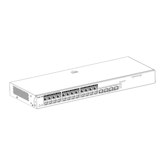
- Page 13 Ruijie RG-NBS3100 Series Switches Hardware Installation and Reference Guide Product Overview Front Panel Figure 1-9 Front Panel of the RG-NBS3100-8GT2SFP Note: 1. System status LED 5. 1000 Base-X SFP port 2. Reset button 6. SFP port status LED 3. 10/100/1000 Base-T Ethernet port 7.
- Page 14 Ruijie RG-NBS3100 Series Switches Hardware Installation and Reference Guide Product Overview Note: 1. Protective earthing terminal 2. Hole for anti-theft lock This device relies on the separate protective earthing terminal. The device installation must be permanently grounded. The device must be intended to be used in a location with equipotential bonding (such as a telecommunication center, a dedicated computer room, or a restricted access area).
- Page 15 Ruijie RG-NBS3100 Series Switches Hardware Installation and Reference Guide Product Overview information. 1000Base-X SFP Port 100Base-FX AC input Rated voltage range: 100 V to 240 V Maximum voltage range: 90 V to 264 V Power Supply Frequency: 50/60 Hz...
- Page 16 Ruijie RG-NBS3100 Series Switches Hardware Installation and Reference Guide Product Overview On the front panel, the RG-NBS3100-8GT2SFP-P Ethernet switch provides 8 10/100/1000Base-T Ethernet ports, 2 SFP ports, 1 reset button, and 1 PoE mode switch-over button. On the back panel, it provides an AC power port.
- Page 17 Ruijie RG-NBS3100 Series Switches Hardware Installation and Reference Guide Product Overview Note: 1. Protective earthing terminal 3. Power cord retention clips 2. Hole for anti-theft lock 4. Three-hole AC power receptacle This device relies on the separate protective earthing terminal.
-
Page 18: Preparation Before Installation
Ruijie RG-NBS3100 Series Switches Hardware Installation and Reference Guide Preparation before Installation 2 Preparation before Installation 2.1 Safety Suggestions To avoid personal injury and device damage, carefully read the safety suggestions before you install the RG-NBS3100 series. The following safety suggestions do not cover all possible dangers. -
Page 19: Installation Site Requirements
Ruijie RG-NBS3100 Series Switches Hardware Installation and Reference Guide Preparation before Installation action current of the leakage protector/2/maximum leakage current of each power supply = 30/2/1 .5 = 10). In other words, the leakage protector with 30 mA rated action current supports no more than ten power supplies. In this case, the twenty power supplies in the system require at least two leakage protectors with 30 mA rated action current and each leakage protector supports ten power supplies. - Page 20 Ruijie RG-NBS3100 Series Switches Hardware Installation and Reference Guide Preparation before Installation recommended that you clean the switch at regular intervals (like once every three months). In particular, avoid dust from blocking the screen mesh on the back of the cabinet.
- Page 21 Ruijie RG-NBS3100 Series Switches Hardware Installation and Reference Guide Preparation before Installation Average (mg/m3) Maximum (mg/m3) The average and maximum values are measured for a week. The switch cannot be placed in the environment with the maximum density for over 30 minutes every day.
- Page 22 Ruijie RG-NBS3100 Series Switches Hardware Installation and Reference Guide Preparation before Installation The sectional area of the protective grounding wire should be at least 0.75 mm (18 AWG). Use the 3-core power supply line. The sectional area of each pin should be at least 0.75 mm or 18 AWG.
-
Page 23: Installation Tools
Ruijie RG-NBS3100 Series Switches Hardware Installation and Reference Guide Preparation before Installation For the TN AC power supply system, the single-phase three-core power socket with protective earthing conductors (PE) should be adopted to effectively filter out interference from the power g rid through filtering circuits. -
Page 24: Product Installation
Ruijie RG-NBS3100 Series Switches Hardware Installation and Reference Guide Product Installation 3 Product Installation 3.1 Installation Flowchart 3.2 Confirmations Before Installation Before installation, confirm the following points: Check whether ventilation requirements are met for the switch. - Page 25 Ruijie RG-NBS3100 Series Switches Hardware Installation and Reference Guide Product Installation Check whether the requirements of temperature and humidity are met for the switch. Check whether power cables are already laid out and whether the requirements of ele ctrical current are met.
- Page 26 Ruijie RG-NBS3100 Series Switches Hardware Installation and Reference Guide Product Installation Step 2: Use the supplied M6 screws and cage nuts to securely attach the mounting brackets to the rack, as shown in Figure 3-3, Figure 3-4, Figure 3-5, and Figure 3-6.
-
Page 27: Grounding The Switch
Ruijie RG-NBS3100 Series Switches Hardware Installation and Reference Guide Product Installation Figure 3-6 Attaching the Brackets to the Rack (24-Port Switch) 3.3.2 Mounting the Switch on a Table Attach the four rubber pads to the recessed areas on the bottom of the switch, as shown in Figure 3-7 and Figure 3-8. -
Page 28: Connecting External Cables
Ruijie RG-NBS3100 Series Switches Hardware Installation and Reference Guide Product Installation Determine the sectional area of the grounding wire according to the possible maximum current, and use cables of the good conductor. Do not use bare wires. ... -
Page 29: Checking After Installation
Ruijie RG-NBS3100 Series Switches Hardware Installation and Reference Guide Product Installation On both sides of the chassis, fasten the fibers and twisted pairs to the cabinet cable management ring or ca bling chute. For power cables, bundle them closely along the bottom of the chassis, in a straight line wherever possible. -
Page 30: System Commissioning
Ruijie RG-NBS3100 Series Switches Hardware Installation and Reference Guide System Commissioning 4 System Commissioning 4.1 Establishing the Configuration Environment Establishing the Configuration Environment Use the network cable to connect a PC to the switch. Figure 4-1 Configuration Environment Connecting the Console Cable ... - Page 31 Ruijie RG-NBS3100 Series Switches Hardware Installation and Reference Guide System Commissioning The console cable is correctly connected; the PC is already started; parameters are configured. Checking After Power-on (Recommended) After power-on, you are advised to perform the following checks to ensure the normal operation of follow -up configurations.
-
Page 32: Troubleshooting Flowchart
Ruijie RG-NBS3100 Series Switches Hardware Installation and Reference Guide Troubleshooting 5 Troubleshooting 5.1 Troubleshooting Flowchart 5.2 Troubleshooting Common Faults Symptom Possible Causes Solution management A password is manually configured but Press the reset button to restore the default interface login it is forgotten. - Page 33 Ruijie RG-NBS3100 Series Switches Hardware Installation and Reference Guide Troubleshooting Check whether the power socket is normal. The status LED is off The power supply is not enabled, or the Check whether the power cable is correctly after power-on. power cable is loosened.
-
Page 34: Appendix A Connectors And Connection Media
Ruijie RG-NBS3100 Series Switches Hardware Installation and Reference Guide Appendix A Connectors and Connection Media Appendix A Connectors and Connection Media 1000BASE-T/100BASE-TX/10BASE-T Ports The 1000BASE-T/100BASE-TX/10BASE-T supports adaptation of three rates and automatic MDI/MDIX crossover at these three rates. The 1000BASE-T complies with IEEE 802.3ab, and uses the cable of 100-ohm Category-5 or Supper Category-5 UTP or STP, which can be up to 100 m. - Page 35 Ruijie RG-NBS3100 Series Switches Hardware Installation and Reference Guide Appendix A Connectors and Connection Media Optical Fiber Connection For the optical fiber ports, select single-mode or multimode optical fibers for connection according to the fiber module connected. Figure A-4 shows the connection schematic diagram.
-
Page 36: Appendix B Mini-Gbic And Spf Module
Ruijie RG-NBS3100 Series Switches Hardware Installation and Reference Guide Appendix B Mini-GBIC and SPF Module Appendix B Mini-GBIC and SPF Module SFP modules (mini-GBIC module) and 10G SFP+ modules are available to cope with interface types of switch modules. You can select the mini-GBIC module to suit your specific needs. The models and technical specifications of some mini-GBIC and 10G SFP+ modules are listed below. - Page 37 Ruijie RG-NBS3100 Series Switches Hardware Installation and Reference Guide Appendix B Mini-GBIC and SPF Module GE-SFP-SX -9.5 GE-SFP-LX 1310 -9.5 SFP-MM850 -9.5 SFP-SM1310 1310 -9.5 Table B-2 Models and Technical Specifications of the Mini-GBIC-GT Module Standard 1000Base-T SFP Type DDM (Yes/No)
- Page 38 Ruijie RG-NBS3100 Series Switches Hardware Installation and Reference Guide Appendix B Mini-GBIC and SPF Module Rate/Distance Module Pairs GE-SFP-SX-SM1310-BIDI 1000 Mbps/500 m GE-SFP-SX-SM1550-BIDI GE-SFP-LX20-SM1310-BIDI 1000 Mbps/20 km GE-SFP-LX20-SM1550-BIDI GE-SFP-LH40-SM1310-BIDI 1000 Mbps/40 km GE-SFP-LH40-SM1550-BIDI The BIDI modules must be used in pairs , for example, FE-SFP-LX20-SM1310-BIDI and FE-SFP-LX20-SM1550-BIDI...
-
Page 39: Appendix C Surge Protection
Ruijie RG-NBS3100 Series Switches Hardware Installation and Reference Guide Appendix C Surge Protection Appendix C Surge Protection Installing the AC Power Arrester (Surge Protection Cable Row) The external surge protection cable row must be used on the AC power port to prevent the switch from being struck by lightning when the AC power cable is introduced from the outdoor and directly connected to the power port of the switch. - Page 40 Ruijie RG-NBS3100 Series Switches Hardware Installation and Reference Guide Appendix C Surge Protection During the switch usage, the Ethernet port arrester must be connected to the switch to prevent the switch damage by lightning before the outdoor network cable connects to the switch.
- Page 41 Ruijie RG-NBS3100 Series Switches Hardware Installation and Reference Guide Appendix C Surge Protection Poor arrester grounding: The grounding line must be as short as possible to ensure that it is in good contact with the switch grounding terminal. Use the multimeter to confirm the contact after grounding.
-
Page 42: Appendix D Cabling Recommendations
Ruijie RG-NBS3100 Series Switches Hardware Installation and Reference Guide Appendix D Cabling Recommendations Appendix D Cabling Recommendations When RG-NBS3100 series switches are installed in standard 19-inch cabinets, cables are tied in the binding rack on the cabinet by the cabling rack, and top or bottom cabling is adopted according to the actual situation in the equipment room. - Page 43 Ruijie RG-NBS3100 Series Switches Hardware Installation and Reference Guide Appendix D Cabling Recommendations Route and bundle power, signal, ground cables separately. When the cables are close to each other, cross them. When power cables are parallel to signal cables, the distance between them must be 30 mm (1.18 in.).
- Page 44 Ruijie RG-NBS3100 Series Switches Hardware Installation and Reference Guide Appendix D Cabling Recommendations Wrap up unnecessary or excess cables and bind them to the appropriate rack position, where device operation is not affected and no damages occur to the device and cables during commissioning.
- Page 45 Ruijie RG-NBS3100 Series Switches Hardware Installation and Reference Guide Appendix D Cabling Recommendations Diameter of Cable Bundle (mm) Space Between Bundles (mm) 80 to 150 10 to 30 150 to 200 200 to 300 No knot is allowed in cabling or bundling.
-
Page 46: Appendix E Site Selection
Ruijie RG-NBS3100 Series Switches Hardware Installation and Reference Guide Appendix E Site Selection Appendix E Site Selection The equipment room should be at least 5 km away from the heavy pollution source such as the smelter, coal mine , and thermal power plant, 3.7 km away from the medium pollution source such as the chemical industry, rubber...
Need help?
Do you have a question about the Ruijie RG-NBS3100 Series and is the answer not in the manual?
Questions and answers