
Subscribe to Our Youtube Channel
Related Manuals for Reyee ES NBS Series


Summary of Contents for Reyee ES NBS Series
- Page 1 Reyee ES_NBS Series Switch Cookbook Document Version: V1.2 Date: 2022.11.25 Copyright © 2022 Ruijie Networks...
- Page 2 Copyright Copyright © 2022 Ruijie Networks All rights are reserved in this document and this statement. Without the prior written consent of Ruijie Networks, any organization or individual shall not reproduce, extract, back up, modify, or propagate the content of this document in any manner or in any form, or translate it into other languages or use some or all parts of the document for commercial purposes.
-
Page 3: Preface
This document is intended for: Network engineers Technical support and servicing engineers Network administrators Technical Support The official website of Ruijie Reyee: https://www.ruijienetworks.com/products/reyee Conventions GUI Symbols Interface Description Example symbol 1. Button names 1. Click OK. - Page 4 Instruction This manual is used to guide users to understand the product, install the product, and complete the configuration. The example of the port type may be different from the actual situation. Please proceed with configuration according to the port type supported by the product. The example of display information may contain the content of other product series (such as model and description).
-
Page 5: Table Of Contents
Contents Preface ..............................I 1 Product Introduction ........................13 1.1 Reyee ES200 Switch ....................... 13 1.1.1 Product List ........................13 1.1.2 LED Indicator ....................... 14 1.1.3 Button ........................... 14 1.2 Reyee NBS Switch........................15 1.2.1 Product List ........................16 1.2.2 LED Indicator ....................... 17 1.2.3 Button ........................... - Page 6 3.2.1 Quick provisioning via Ruijie Cloud APP ..............26 3.2.2 Quick provisioning via Reyee EWeb................36 4 Reyee ES Series Switches Configuration ............. 错误 ! 未定义书签。 ES Series Switches Port Settings ....................39 4.1 Managing Port Information ...................... 39 4.1.1 Port Status Bar ......................
- Page 7 5.1.4 Configuring Static MAC Address ................. 49 5.2 VLAN Settings .......................... 50 5.2.1 Global VLAN Settings ....................50 5.2.2 Static VLANs Settings ....................50 5.2.3 Port VLAN Settubgs ..................... 51 6 ES Series Switches Security ......................53 6.1 DHCP Snooping ........................53 6.1.1 Overview ........................
- Page 8 9.1 Cable Diagnostics ........................59 9.2 Multi-DHCP Alarming ....................... 59 9.3 Viewing Switch Information...................... 60 Reyee NBS Series Switches Configuration ............. 错误 ! 未定义书签。 10 NBS Series Network management ....................61 10.1 Overviewing Network Information ..................61 10.2 Viewing Networking Information .................... 61 10.3 Adding Networking Devices ....................
- Page 9 11.1.2 Hardware Monitor Information ................... 80 11.1.3 Port Info ........................81 11.2 Port Flow Statistics ........................ 83 11.3 MAC Address Management ....................83 11.3.1 Overview ........................83 11.3.2 Displaying the MAC Address Table ................84 11.3.3 Displaying Dynamic MAC Address ................85 11.3.4 Configuring Static MAC Binding .................
- Page 10 12.3.2 Overview ........................105 12.3.3 Aggregate Port Configuration .................. 106 12.3.4 Configuring a Load Balancing Mode ............... 108 12.4 Port Mirroring ........................109 12.4.1 Overview ........................109 12.4.2 Procedure ......................... 109 12.5 Rate Limiting ........................111 12.6 MGMT IP Configuration ....................... 113 12.7 Out-of-Band IP Configuration ....................
- Page 11 13.4.3 Configuring the MVR Ports ..................126 13.5 Configuring Multicast Group ....................127 13.6 Configuring a Port Filter ....................... 129 13.6.1 Configuring Profile ....................129 13.6.2 Configuring a Range of Multicast Groups for a Profile ..........130 13.7 Setting an IGMP Querier ..................... 132 13.7.1 Overview ........................
- Page 12 15.2.2 Procedure ......................... 146 15.3 ACL ............................147 15.3.1 Overview ........................147 15.3.2 Creating ACL Rules ....................147 15.3.3 Applying ACL Rules ....................150 15.4 Port Protection ........................151 15.5 IP-MAC Binding ........................151 15.5.1 Overview ........................151 15.5.2 Procedure ......................... 152 15.6 IP Source Guard ........................
- Page 13 16.2.3 Applying LLDP to a Port ................... 164 16.2.4 Displaying LLDP information ................... 165 16.3 RLDP ............................ 166 16.3.1 Overview ........................166 16.3.2 Standalone Device Configuration ................166 16.3.3 Batch Configuring Network Switches ..............169 16.4 Configuring the Local DNS ....................171 16.5 Voice VLAN ..........................
- Page 14 17.2 Network Tools ........................181 17.2.1 Ping .......................... 181 17.2.2 Traceroute ........................ 182 17.2.3 DNS Lookup ......................183 17.3 Fault Collection ........................184 17.4 Cable Diagnostics ........................ 184 17.5 System Logs ........................185 17.6 Alerts ............................ 185 18 NBS Series System Configuration ....................188 18.1 Setting the System Time ......................
- Page 15 19.7.2 Configuring a Global Blacklist/Whitelist ............... 9 19.7.3 Configuring an SSID-based Blacklist/Whitelist ............10 19.8 Wireless Network Optimization with One Click ..............10 19.9 Enabling the Reyee Mesh Function..................12 19.10 Configuring the AP Ports ..................... 12 20 Advanced Solution Guide ........................ 1 20.1 Reyee Flow Control Solution ....................
- Page 16 21.1 Reyee Password FAQ ((collection)) ..................49 21.2 Reyee Flow Control FAQ((collection)) ................... 49 21.3 Reyee Self-Organizing Network ( SON) FAQ ((collection)) ..........49 21.4 Reyee series Devices Parameters Tables ................49 21.5 Reyee Parameter Consultation FAQ ((collection)) ..............49...
-
Page 17: Product Introduction
Product Introduction Reyee ES200 Switch Ruijie Reyee smart surveillance switches offer a variety of port options to meet the needs of video surveillance networks of different scales. Ruijie Reyee smart surveillance switches support full-power PoE output to ensure that all cameras can be powered simultaneously when connected to the switch at maximum capacity. In addition,... -
Page 18: Led Indicator
10/100 Base-T Auto- 10/100/1000 Base-T Auto- 1000Base-X SFP Console Model sensing Ethernet Port sensing Ethernet Port Port Port RG-ES224GC RG-ES216GC The SPF ports cannot be downward compatible with 100Base-FX. 1000Base-T is compatible with 100Base-TX and 10Base-T in the downlink direction. 1.1.2 LED Indicator State... -
Page 19: Reyee Nbs Switch
RG-NBS3200 series switch is a new generation of high-performance, strong security and integrated multi- service layer 2 Ethernet switch launched by Reyee. This series of switches adopts an efficient hardware architecture design, providing larger entry specifications and faster Hardware processing performance, more convenient operation experience. -
Page 20: Product List
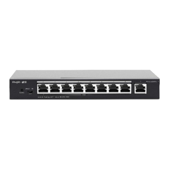
1.2.1 Product List 10/100/1000 1000Base-X Console Power Model 10G SFP+ Port Base-T Ethernet Port Supply Port Port RG-NBS3100- Single 24GT4SFP RG-NBS3100- 24 (Support PoE+) Single 24GT4SFP-P RG-NBS3100- Power 8GT2SFP adapter RG-NBS3100- 8 (Support PoE+) Single 8GT2SFP-P RG-NBS3200- Single 24GT4XS RG-NBS3200- 24SFP/8GT4 8 (combo) Single... -
Page 21: Led Indicator
RG-NBS5100- Single 24GT4SFP RG-NBS5100- Single 48GT4SFP RG-NBS5200- Single 24GT4XS RG-NBS5200- 24SFP/8GT4 8 (combo) Single RG-NBS5200- Single 48GT4XS SFP port is downward compatible with 100Base-FX. 1000Base-T is downward compatible with 100Base-TX and 10Base-T. Combo port consists of one 1000Base-X SFP port and one 10/100/1000Base-T Ethernet port. That is, only one port of them is available at a particular time. -
Page 22: Button
The Web client usually refers to a browser, such as Google Chrome IE, or Firefox. The Reyee managed switches not only support Web interface management, but also support life-time-free Ruijie Cloud App and Ruijie Cloud platform remote management. Users can view the network status, modify the configuration, and troubleshooting at home. - Page 23 Enter the password on the login page and click “Login”. Default Password: admin For the Reyee EG device, you may use either 192.168.110.1 or 10.44.77.254 to access the device. For the Reyee switches, you may use 10.44.77.200 to access the device.
-
Page 24: Configuring Password
Configuring Password Upgrading Login to the eWeb of the device and choose Router--System--Upgrade. Backing up and Resetting Login in the eWeb of the device and choose Router--System--Management. -
Page 25: Restoring Factory Settings
Login in the eWeb of the device and click Network--Reboot&Reset, then you can reset your devices. Restoring Factory Settings Login in the eWeb of the device Reset all device in the network. -
Page 26: Getting Start
Getting Start Preparing for Installation 3.1.1 Safety Suggestions To avoid personal injury and equipment damage, please carefully read the safety suggestions before you install each device. The following safety suggestions do not cover all possible dangers 1. 3.1.1.1 Installation a) Keep the chassis clean and free from any dust. b) Do not place devices in a walking area. -
Page 27: Installation Site Requirement
5. 3.1.1.5 Laser Some devices support varying models of optical modules sold on the market which are Class I laser products. Improper use of optical modules may cause damage. Therefore, pay attention to the following when you use them: a) When a fiber transceiver works, ensure that the port has been connected with an optical fiber or is covered with a dust cap, to keep out dust and avoid burning your eyes. -
Page 28: Network Planning
Lightning Grounding The lightning protection system of a facility is an independent system that consists of the lightning rod, download conductor and the connector to the grounding system, which usually shares the power reference ground and yellow/green safety cable ground. The lightning discharge ground is for the facility only, irrelevant to the equipment. - Page 29 Following ports are used for Ruijie Cloud management. To let devices go online on Ruijie Cloud, ensure these ports are available and the data stream is permitted in this network.
-
Page 30: Quick Provisioning
Quick Provisioning 3.2.1 Quick provisioning via Ruijie Cloud APP The network topology shown in the below picture includes the Reyee gateway, Reyee POE switch and Reyee RAP. 1. 3.2.1.1 Create a project Open Ruijie Cloud App and Click Create a Project, then select Connect to Wi-Fi. - Page 31 After click Yes, then Cloud App will prompt you to connect @Ruijie-mxxxx SSID. Note: @Ruijie-mxxxx is generated after network self-organization established successfully, while @Ruijie-sxxxx is generated on a standalone device, xxxx is the last four letters of mac address of device.
- Page 32 Connect the @Ruijie-mxxxx SSID on your phone.
- Page 33 After connected the @Ruijie-mxxxx SSID, the Cloud App will prompt to generate topology and detect all devices in this SON.
- Page 34 After all devices were detected, Cloud App will display them and show the topology, shown in the below picture. Click Start Config to perform the basic configuration of this project.
- Page 35 2. 3.2.1.2 Configure the project Input the Project Name and Management Password.
- Page 36 Then select the scenario of this project based on your requirement.
- Page 37 3. 3.2.1.3 Configure the internet For configuring WAN, you can chose PPPoE, DHCP and Static IP.
- Page 38 4. 3.2.1.4 Configure the SSID For SSID settings, input the name of SSID and configure it as open or configure password for this SSID. Select the region code.
- Page 39 The configuration will be synchronized to the network After about 3s, Ruijie Cloud App will prompt that the configuration is delivery succeed.
-
Page 40: Quick Provisioning Via Reyee Eweb
Connect to the SSID created just now to manage the whole network on Cloud App. 3.2.2 Quick provisioning via Reyee EWeb The network topology shown in the below picture includes the Reyee gateway, Reyee POE switch and Reyee RAP. - Page 41 Connect PC to POE switch, set the ip address of PC as static ip address 192.168.110.x, then input 192.168.110.1 on the browser to login the EWEB of EG. All devices in this networks will display in EWEB. Click the Start Setup to perform the quick start of this network.
- Page 42 After the configuration has been delivery and activated, you can enter the overview interface to manage the SON of Reyee devices.
-
Page 43: Es Series Switches Port Settings
ES Series Switches Port Settings Managing Port Information 4.1.1 Port Status Bar The port status bar is at the top of the web page, showing port ID, port attribute (uplink/downlink), and the connection status. Click Collapse to hide the port status bar. Different colors and shapes of the port icons represent different port statuses. - Page 44 Table 4-1 Port Icons Port Icon Description The port icon is in the shape of a square, showing the port is a fiber port. The port icon is in the shape of an RJ-45 connector, showing the port is a copper port. The color of the port icon is black, showing the port is disconnected.
-
Page 45: Port Info Overview
4.1.2 Port Info Overview Choose Homepage. The homepage displays the global port information, including the port status, the packet receiving/transmission rate (Rx/Tx rate), port isolation status and loop detection status. Besides, it supports searching for the downlink device. Click Port Status to configure the basic port attributes. For details, see Chapter 2.2. Click Isolation Status to configure port isolation so that the downlink ports of the device are isolated from each other. -
Page 46: Port Settings
4.2.1 Port Settings Users can set the basic attributes of the Ethernet ports in batches. Click Select in the Port column to display options of all device ports. Select the ports you want to configure, and then select the port status, port rate, port duplex mode, flow control status, and click Save. Table 4-2 Basic Port Configuration Parameters Parameter... -
Page 47: Port Status
Caution Shutting down all ports will make the switch unmanageable. Exercise caution when performing this operation. 4.2.2 Port Status Users can view the configuration status of the port attributes and check whether these configurations are active, including the port rate, duplex mode, and flow control status. Port Mirroring 4.3.1 Overview... -
Page 48: Port Isolation
Caution ● You can select multiple source ports but only one mirror port. The source ports cannot contain the mirror port. ● For RG-ES205C-P, RG-ES205GC-P, RG-ES209C-P, RG-ES209GC-P switches, the mirror port only supports packet capture and cannot transmit data with switches. Table 4-3 Port Mirroring Parameters Parameter... -
Page 49: Port-Based Rate Limiting
Caution The number of the uplink/downlink ports and port IDs of different devices vary. Please refer to the actual information of the device. Port-based Rate Limiting Choose QoS Settings > Port Rate. Users can configure rate limiting rules for packets in the input direction and the output direction of ports. There is no rate limiting on ports by default. -
Page 50: Management Ip Address
Note ● The rate limiting range for RG-ES205C-P switch ports is from 1 to 100M. ● The maximum rate supported by port 1 to port 8 of RG-ES209C-P switch is 100M. If the configured rate exceeds 100M, the effective rate will still be 100M. The rate limiting range for port 9 is from 1 to 1000M. ●... -
Page 51: Dc Port Reboot
● You are advised to bind a configured management VLAN to an uplink port. Otherwise, you may fail to access the web management system. For details, see Chapter 3.2.3. ● If you disable Auto Obtain IP feature, multi-DHCP alarming will fail. For details about multi-DHCP alarming, see Chapter 7.2. -
Page 52: Es Series Switches Switch Settings
ES Series Switches Switch Settings Managing MAC Address 5.1.1 Overview The MAC address table records mappings of MAC addresses and ports to VLANs. The device queries the MAC address table based on the destination MAC address in a received packet. If the device finds an entry that is consistent with the destination MAC address in the packet, the device forwards the packet through the port specified by the entry in unicast mode. -
Page 53: Configuring Static Mac Address
Caution If you disable VLAN, the VLAN ID will not be recorded in the MAC address table.MAC address entries can only be found through MAC address. Enter MAC address and VLAN ID, and then click Search. The MAC address entries that meet the search criteria will be displayed in table right below the Search button. -
Page 54: Vlan Settings
VLAN Settings 5.2.1 Global VLAN Settings Choose Homepage > Device Info. This page displays the status of VLAN settings. Toggle the on-off switch to enable or disable VLAN settings. When VLAN is disabled, the device operates like an un-managed switch. The device forwards packets according to the destination MAC address, and the VLAN information of the forwarding packets remains unchanged during the forwarding process. -
Page 55: Port Vlan Settubgs
Note ● The VLAN ID ranges from 1 to 4094. VLAN 1 is the default VLAN. ● The default VLAN (VLAN 1), Management VLAN, Native VLAN, Permit VLAN, and Access VLAN cannot be deleted. 5.2.3 Port VLAN Settubgs Caution Users can configure port VLAN only when the global VLAN settings feature is enabled. For details, see Chapter 3.2.1. - Page 56 Access One access port can belong to only one VLAN and allow frames from this VLAN only to pass through. This VLAN is called an access VLAN. The frames from the access port do not carry VLAN tag. When the access port receives an untagged frame from a peer device, the local device determines that the frame comes from the access VLAN and adds the access VLAN ID to the frame.
-
Page 57: Es Series Switches Security
ES Series Switches Security DHCP Snooping 6.1.1 Overview The Dynamic Host Configuration Protocol (DHCP) snooping function allows a device to snoop DHCP packets exchanged between clients and a server to record and monitor the IP address usage and filter out invalid DHCP packets, including request packets from the clients and response packets from the server. -
Page 58: Configuration Steps
beyond the range until the packet rate falls within the range. This prevents flooded data from entering the LAN and causing a storm. 6.2.2 Configuration Steps Choose QoS Settings > Storm Control. Select the storm control type, port, status, and enter the rate limit, and then click Save. The storm control type and corresponding rate are displayed in the table right below the Save button. -
Page 59: Es Series Switches Poe Settings
ES Series Switches PoE Settings Caution Only RG-ES226GC-P, RG-ES218GC-P, RG-ES209GC-P, RG-ES209C-P, RG-ES205GC-P, RG-ES205C-P, and RG-FS306-P switches support the PoE function. Choose PoE Settings. The device supports PoE power supply. Users can view and configure the current power status. Device status: The total power, used power, remaining power, and current work status of the PoE system are displayed. -
Page 60: Es Series Switches System Settings
ES Series Switches System Settings Managing Device Information 8.1.1 Viewing Device Information Choose Homepage > Device Info. The device information is displayed on the homepage, including hostname, device model, serial number, firmware version, IP address, MAC address, cloud status, and uptime. Click Device Info to access the Device Info page (System Settings >... -
Page 61: Cloud Management
8.1.3 Cloud Management Choose Homepage > Device Info. Cloud status displays whether the device is connected to the cloud. After the device is bound to a cloud management account, the Cloud Status will display Connected, and users can manage the device remotely through Ruijie Cloud webpage or APP. -
Page 62: Device Reboot
Device Reboot Choose System Settings > Reboot. Click Reboot to reboot the switch. System Upgrade 8.4.1 Local Upgrade Choose System Settings > Upgrade. Click Select File to select the upgrade package from the local files (the upgrade package is a bin file. If it is a tar.gz file, users need to decompress the package and select the bin file for upgrade). -
Page 63: Restoring Factory Configuration
Restoring Factory Configuration Choose System Settings > Restore Default. Click Restore to restore factory configuration and reboot the device. ES Series Switches Monitoring Cable Diagnostics Choose Monitoring > Cable Diagnostics. Cable diagnostics allows users to check the status of Ethernet cables. For example, users can check whether the cables are short-circuited or disconnected. -
Page 64: Viewing Switch Information
● Multi-DHCP alarming will fail when the device IP address is not obtained dynamically. For relevant IP address configuration, see Chapter 2.6. Choose Homepage. When there are multiple DHCP servers in a LAN, the system will send a conflicting alarm. An alarming message will be displayed in the Device Info column. -
Page 65: Nbs Series Network Management
NBS Series Network management 10.1 Overviewing Network Information In network mode, the Overview page displays the current network topology, uplink and downlink real-time traffic, network connection status, and number of users and provides short-cut entries for configuring the network and devices. - Page 66 Click a traffic data item to view the real-time total traffic information. Click a device in the topology to view the running status and configuration of the device and configure device functions. By default, the product model is used as the device name. Click to modify the device name so that the description can distinguish devices from one another.
- Page 67 The update time is displayed in the lower-left corner of the topology view. Click Refresh to update the topology to the latest state. It takes some time to update the topology data. Please wait patiently.
-
Page 68: Adding Networking Devices
10.3 Adding Networking Devices 10.3.1 Wired Connection (1) When a new device connects to an existing device on the network, the system displays the message “A device not in SON is discovered.” and the number of such devices in orange under “Devices” on the upper-left corner of the [Overview] page. - Page 69 (3) You do not need to enter the password if the device to add is newly delivered from factory. If the device has a password, enter the configuring password of the device. Device addition fails if the password is incorrect.
-
Page 70: Ap Mesh
Caution To scan the AP, the Reyee Mesh function must be enabled on the current network. (For details, see 0.) The AP should be powered on nearby. It may fail to be scanned in case of long distance or obstacle blocking. - Page 71 Click the device SN to configure the specified device separately.
-
Page 72: Configuring The Service Network
Check offline devices and click Delete Offline Devices to remove them from the list and networking topology. 10.5 Configuring the Service Network The wireless and wired network configurations of the current network are displayed in the lower-left of the Overview page. - Page 73 (2) Configure a VLAN for wired access, specify the address pool server for access clients in this VLAN, and determine whether to create a new DHCP address pool. A switch or gateway device can be selected as the address pool server.
-
Page 74: Configuring The Wireless Network
(4) Confirm that the configuration items to be delivered are correct and then click Save. Wait a moment for the configuration to take effect. 10.5.2 Configuring the Wireless Network (1) Click Add Wi-Fi VLAN to add wireless network configuration, or select an existing Wi-Fi VLAN and click Setup to modify its configuration. - Page 75 (2) Set the Wi-Fi name, Wi-Fi password, and applicable bands. Click Next. (3) Configure a VLAN for wireless access, specify the address pool server for access clients in this VLAN, and determine whether to create a new DHCP address pool. A switch or gateway device can be selected as the address pool server.
-
Page 76: Processing Alerts
(4) Confirm that the configuration items to be delivered are correct and then click Save. Wait a moment for the configuration to take effect. 10.6 Processing Alerts Choose Network > Overview. If a network exception occurs, alert message on this exception and the corresponding solution are displayed on the Overview page. -
Page 77: Viewing Online Clients
10.7 Viewing Online Clients The Clients in the upper-left corner of the Overview page displays the total number of online clients in the current network; moving the cursor to the number of users will display the number of current wired users, wireless users in the 2.4GHz band, and wireless users in the 5GHz band. - Page 78 Click to switch to the online clients page (or click Clients > Online Clients). Table 10-1 Description of Online Client Information Field Description Indicate the name and access type of the client. The access type can Username/Type be wireless or wired. Indicate the SN of the device that the user accesses to.
-
Page 79: Smart Device Network
10.8 Smart Device Network Caution Currently, the function is supported by RG-NBS6002 Series, RG-NBS7003 Series and RG-NBS7006 Series devices. 10.8.1 Overview The smart device network is used to quickly plan and set up an isolation network for smart clients, so as to isolate the client network from the normal service network and other types of clients, and improve the stability of the network. - Page 80 (3) Display the identified client and client server information, including IP address, MAC address, SN number of the connected switch and connection port. Click to view the detailed information. If the connection information to the client server is not identified, you need to click Configure and fill in the relevant information manually. After confirming that the client device information is correct, click Isolate Client.
- Page 81 (4) Input the name of the VLAN, VLAN ID, gateway address, and subnet mask of the isolated client. Check the target network segment and click Generate Config. (5) After confirming the configuration, click Deliver Config. If you need to modify it, you can click Previous to return to the setting page.
- Page 82 (7) After completing the smart device network settings, you can view the client monitoring information on the page, including client online status, connection information, device information, and online and offline time. Select the client entry and click Delete Client to remove the specified client from the current network. Click Batch Edit Hostnames to import a txt file containing client IP and client name (one line for each client, each line contains an IP and a name, and the IP and the name are separated by the Tab key), and modify the client names in batches.
-
Page 83: Nbs Series Basic Management
NBS Series Basic Management 11.1 Overviewing Switch Information 11.1.1 Basic information about the Device Choose Local Device > Home > Basic Info. Basic information includes device name, device model, SN number, software version, management IP, MAC address, networking status, system time, working mode, etc. 1. -
Page 84: Hardware Monitor Information
2. Switching the Work Mode Click the current work mode to change the work mode. 3. Setting MGMT IP Click current management IP address to jump to the management IP configuration page. For more information, 12.6 11.1.2 Hardware Monitor Information Caution Only RG-NBS6002 Series, RG-NBS7003 Series and RG-NBS7006 Series devices support displaying this type of information. -
Page 85: Port Info
11.1.3 Port Info Choose Local Device > Home > Port Info. The port info page displays the details of all ports currently on the switch. Click Panel View to view the port roles and statuses corresponding to port icons of different colors or shapes. - Page 86 Move the cursor to the icon of a port (for example, Gi14) on the port panel, and more information about the port will be displayed, including the port ID, port status, port rate, uplink and downlink traffic, transmission rate, and optical/electrical attribute of the port.
-
Page 87: Port Flow Statistics
11.2 Port Flow Statistics Choose Local Device > Monitor > Port Flow. Display traffic statistics such as the rate of the device port, the number of sent and received packets, and the number of error packets. The rate of the port is updated every five seconds. Other traffic statistics are updated every five minutes. -
Page 88: Displaying The Mac Address Table
packet through the interface corresponding to the entry in unicast mode. If the device does not find such an entry, it forwards the packet through all interfaces other than the receiving interface in broadcast mode. MAC address entries are classified into the following types: ... -
Page 89: Displaying Dynamic Mac Address
Note The MAC address entry capacity depends on the product. For example, the MAC address entry capacity of the device shown in the figure above is 32K. 11.3.3 Displaying Dynamic MAC Address Choose Local Device > Monitor > Clients > Dynamic MAC. After receiving the packet, the device will automatically generate dynamic MAC address entries based on the source MAC address of the packet. - Page 90 to the specified port. For example, when 802.1x authentication is enabled on the port, you can configure static MAC address binding to implement authentication exemption. 1. Adding Static MAC Address Entries Choose Local Device > Monitor > Clients > Static MAC. Click Add, enter the MAC address and VLAN VLAN ID, select the port for packet forwarding, and click OK.
-
Page 91: Configuring Mac Address Filtering
Delete an entry: In MAC List, find the entry to be deleted, click Delete in the last Action column. In the displayed dialog box, click OK. 11.3.5 Configuring MAC Address Filtering To prohibit a user from sending and receiving packets in certain scenarios, you can add the MAC address of the user to a filtering MAC address entry. -
Page 92: Configuring Mac Address Aging Time
2. MAC Filter Choose Local Device > Monitor > Clients > MAC Filter. Batch delete: In MAC List, select the MAC address entries to be deleted and click Delete Selected. In the displayed dialog box, click OK. Delete an entry: In MAC List, find the entry to be deleted, click Delete in the last Action column. In the displayed dialog box, click OK. -
Page 93: Vlan
The Address Resolution Protocol (ARP) is used to resolve IP addresses into MAC addresses. ARP can obtain the MAC Address associated with an IP address. ARP stores the mappings between IP addresses and MAC addresses in the ARP cache of the device. The device learns the IP address and MAC address of the network devices connected to its interfaces and generates the corresponding ARP entries. - Page 94 1. Adding a VLAN Create multiple VLANs: Click Batch Add. In the displayed dialog box, enter VLAN ID range (separate multiple VLAN ID ranges with commas (,)), and click OK. The VLANs added will be displayed in VLAN List. Create a VLAN: Click Add. Enter the VLAN ID and description for the VLAN, and click OK. The VLAN added will be displayed in VLAN List.
- Page 95 ● If the device supports L3 functions, VLANs, routed ports, and L3 aggregate ports (L3APs) share limited hardware resources. If resources are insufficient, a message indicating resource insufficiency for VLAN will be displayed. 2. VLAN Description Modifying In VLAN List, Click Edit in the last Action column to modify the description information of the specified VLAN. 3.
-
Page 96: Configuring Port Vlan
11.5.3 Configuring Port VLAN 1. Overview Choose Local Device > VLAN > Port List. Port List displays the VLAN division of the current port. Create VLANs in VLAN List page (see 3.5.2Creating a VLAN) and then configure the port based on the VLANs. You can configure the port mode and VLAN members for a port to determine VLANs that are allowed to pass through the port and whether packets to be forwarded by the port carry the tag field. - Page 97 Port mode Function therefore Native VLAN can only belong to Untag VLAN List. Note Whether the hybrid mode function is supported depends on the product version. 2. Procedure Choose Local Device > VLAN > Port List. Configure port VLANs in a batch: Click Batch Edit, select the port to be configured on the port panel, and select the port mode.
-
Page 98: Batch Switch Configuration
Note ● VLAN ID range is from 1 to 4094, among which VLAN 1 is the default VLAN that cannot be deleted. ● When hardware resources are insufficient, the system displays a VLAN creation failure message. ● Improper configuration of VLANs on a port (especially uplink port) may cause the failure to log in to the Eweb management system. - Page 99 (2) Click Add VLAN to create a VLAN for the selected devices in a batch. If you want to create multiple VLANs, click Batch Add and enter the VLAN ID range, such as 3-5,100. After setting the VLANs, click Next. (3) Configure port attributes for the ports selected in Step 1 in a batch.
-
Page 100: Verifying Configuration
11.5.5 Verifying Configuration View the VLAN and port information of switches to check whether the batch configurations are successfully delivered. -
Page 102: Nbs Series Port Management
NBS Series Port Management 12.1 Overview Ports are important components for data exchange on network devices. The port management module allows you to configure basic settings for ports, and configure port aggregation, switched port analyzer (SPAN), port rate limiting, management IP address, etc. Table 4-1 Description of Port Type Port Type... -
Page 103: Port Configuration
Port Type Note Remarks An L3 aggregate port is a logical aggregate port group composed of multiple physical member ports, just like an L2 aggregate port. The ports to be aggregated must be L3 ports of the same type. An aggregate port serves as the gateway interface of L3 switching. - Page 104 Batch configure: Click Batch Edit, select the port to be configured In the displayed dialog box, select the port switch, rate, work mode, and flow control mode, and click OK to deliver the configuration. In batch configuration, optional configuration items are a common collection of selected ports (that is, attributes supported the selected ports).
- Page 105 Configure one port: In Port List, select a port entry and click Edit in the Action column. In the displayed dialog box, select port status, rate, work mode, and flow control mode, and click OK. Table 4-2 Description of Basic Port Configuration Parameters Parameter Description Default Value...
-
Page 106: Physical Settings
Parameter Description Default Value affected. Set the rate at which the Ethernet physical interface works. Set to Auto means that the port rate is determined by the Rate Auto auto-negotiation between the local and peer devices. The negotiated rate can be any rate within the port capability. Full duplex: realize that the port can receive packets while sending. - Page 107 Batch configure: Click Batch Edit. In the displayed dialog box, select the port to be configured, configure the EEE switch, MTU, enter the port description, and click OK. Note Copper ports and SFP ports cannot be both configured during batch configuration. Configure one port: Click Edit in the Action column of the list.
- Page 108 Table 4-3 Description of Physical Configuration Parameters Parameter Description Default Value It is short for energy-efficient Ethernet, which is based on the standard IEEE 802.3az protocol. When enabled, EEE saves energy by making the interface enter LPI (Low Power Idle) Disable mode when the Ethernet connection is idle.
-
Page 109: Aggregate Ports
12.3 Aggregate Ports 12.3.1 Aggregate Port Overview An aggregate port (AP) is a logical link formed by binding multiple physical links. It is used to expand link bandwidth, thereby improving connection reliability. The AP function supports load balancing and therefore, evenly distributes traffic to member links. The AP implements link backup. -
Page 110: Aggregate Port Configuration
3. Load Balancing An AP, based on packet characteristics such as the source MAC address, destination MAC address, source IP address, destination IP address, L4 source port ID, and L4 destination port ID of packets received by an inbound interface, differentiates packet flows according to one or several combined algorithms. It sends the same packet flow through the same member link, and evenly distributes different packet flows among member links. - Page 111 2. Modifying Member Ports of a Static Aggregate Port Click an added static aggregate port. Member ports of the aggregate port will become selected. Click a port to deselect it; or select other ports to join the current aggregate port. Click Save to modify the member ports of the aggregate port.
-
Page 112: Configuring A Load Balancing Mode
3. Deleting an Aggregate Port Move the cursor over an aggregate port icon and click upper-right, or select the aggregate port to be deleted, and click Delete Selected to delete the selected aggregate port. After deleted, the corresponding ports become available on the port panel to set a new aggregate port. -
Page 113: Port Mirroring
12.4 Port Mirroring 12.4.1 Overview The switched port analyzer (SPAN) function is a function that copies packets of a specified port to another port that is connected to a network monitoring device, After port mirroring is set, the packets on the source port will be copied and forwarded to the destination port, and a packet analyzer is usually connected to the destination port to analyze the packet status of the source port, so as to monitor all incoming and outgoing packets on source ports. - Page 114 ● A maximum of four SPAN entries can be configured. SPAN cannot be configured for ports that have been used for SPAN.
-
Page 115: Rate Limiting
Table 4-4 Description of Port Mirroring Parameters Default Parameter Description Value A source port is also called a monitored port. Data flows on the source port are monitored for network analysis or troubleshooting. Src Port Support selecting multiple source ports and mirroring multiple ports to one destination port The destination port is also called the monitoring port, that is, the port Dest Port... - Page 116 1. Rate Limiting Configuration Click Batch Edit. In the displayed dialog box, select ports and enter the rate limits, and click OK. You must configure at least the ingress rate or egress rate. After the configuration is completed, it will be displayed in the list of port rate limiting rules.
-
Page 117: Mgmt Ip Configuration
3. Deleting Rate Limiting Batch configure: Select multiple records in Port List, click Delete Selected and click OK in the confirmation dialog box. Configure one port: In Port List, click Delete on the corresponding port entry, and click OK in the confirmation dialog box. -
Page 118: Out-Of-Band Ip Configuration
The device can be networked in two modes: DHCP: Uses a temporary IP address dynamically assigned by the upstream DHCP server for Internet access. Static IP: Uses a static IP address manually configured by users for Internet access. If you select DHCP, the device obtains parameters from the DHCP Server. -
Page 119: Poe Configuration
Note No IP address is configured for the MGMT port by default. Currently, only a static IP address can be configured for the MGMT port but DHCP is not supported. 12.8 PoE Configuration Caution Only PoE switches (The device models are marked with -P) support this function. Choose Local Device >... -
Page 120: Poe Global Settings
12.8.1 PoE Global Settings Choose Local Device > Ports > PoE > PoE Settings. PoE Transmit Power Mode refers to the way that a device allocates power to a connected PD (Powered Device). It supports Auto mode and Energy-saving mode. In Auto mode, the system allocates power based on the classes of PDs detected on ports. -
Page 121: Power Supply Configuration Of Ports
12.8.2 Power Supply Configuration of Ports Choose Local Device > Ports > PoE > Port List. Click Edit in the port entry or click Batch Edit to set the PoE power supply function of the port. -
Page 122: Displaying Global Poe Information
Table 4-6 Description of Parameters for Power Supply Configuration of Ports Parameter Description Default Value Whether to enable the power supply function on the ports Enable By default, the device only supplies power to PDs that comply with the standard IEEE 802.3af and 802.3at protocols. - Page 123 Table 4-7 Description of Port Power Supply Info Field Description Port Device Port ID PoE Status Whether to enable the PoE function on the ports. Transmit Power Status Whether the port supplys power for Pds currently. The power supply priority of the port is divided into three levels: High, Medium, Priority and Low.
-
Page 124: Nbs Series L2 Multicast
NBS Series L2 Multicast 13.1 Multicast Overview IP transmission methods are categorized into unicast, multicast, and broadcast. In IP multicast, an IP packet is sent from a source and forwarded to a specific group of receivers. Compared with unicast and broadcast, IP multicast saves bandwidth and reduces network loads. -
Page 125: Igmp Snooping
Table 5-1 Description of Configuration Parameters of Global Multicast Parameter Description Default Value The Internet Group Management Protocol (IGMP) is a TCP/IP protocol that manages members in an IPv4 multicast group and runs on the multicast devices and hosts residing on the stub of the multicast network, creating and maintaining membership of the multicast group between the hosts and Version... -
Page 126: Enabling Global Igmp Snooping
13.3.2 Enabling Global IGMP Snooping Choose Local Device > Multicast > IGMP Snooping. Turn on IGMP Snooping and click Save. 13.3.3 Configuring Protocol Packet Processing Parameters By controlling protocol packet processing, an L2 multicast device can establish static or dynamic multicast forwarding entries. - Page 127 Table 5-2 Description of VLAN Configuration Parameters of IGMP Snooping Parameter Description Default Value Whether to enable or disable the VLAN multicast function. The multicast function of a VLAN takes effect only when both the Multicast Status Disable global IGMP snooping and VLAN multicast functions are enabled.
-
Page 128: Configuring Mvr
Parameter Description Default Value The device running IGMP Snooping identifies the ports in the VLAN as router ports or member ports. The router port is the port on the Layer 2 multicast device that is connected to the Layer 3 multicast device, and the member port is the host port Dynamic Learning Enable connected to the group on the Layer 2 multicast device. -
Page 129: Configuring Global Mvr Parameters
13.4.2 Configuring Global MVR Parameters Choose Local Device > L2 Multicast > MVR. Click to enable the MVR, select the MVR VLAN, set the multicast group supported by the VLAN, and click Save. Multiple multicast groups can be specified by entering the start and end multicast IP addresses. Table 5-3 Description of Configuring Global MVR Parameters Parameter... -
Page 130: Configuring The Mvr Ports
Parameter Description Default Value Multicast VLAN of a multicast source VLAN Start IP Learned or configured start multicast IP address of an Address MVR multicast group. End IP Learned or configured end multicast IP address of an Address MVR multicast group. 13.4.3 Configuring the MVR Ports Choose Local Device >... -
Page 131: Configuring Multicast Group
Table 5-4 Description of MVR Configuration Parameters of Ports Parameter Description Default Value NONE: Indicates that the MVR function is disabled. SOURCE: Indicates the source port that receives Role NONE multicast data streams. RECEIVER: Indicates the receiver port connected to a client. - Page 132 Table 5-5 Description of Multicast Group Configuration Parameters Parameter Description Default Value VLAN ID VLAN, to which received multicast traffic belongs Multicast IP On-demand multicast IP address Address If the VLAN ID is a multicast VLAN and the multicast address is within the multicast IP address range of the Protocol MVR, the protocol is MVR.
-
Page 133: Configuring A Port Filter
Note Static multicast groups cannot learn other dynamic forwarding ports. 13.6 Configuring a Port Filter Choose Local Device > L2 Multicast > IGMP Filter. Generally, the device running ports can join any multicast group. A port filter can configure a range of multicast groups that permit or deny user access, you can customize the multicast service scope for users to guarantee the interest of operators and prevent invalid multicast traffic. -
Page 134: Configuring A Range Of Multicast Groups For A Profile
Table 5-6 Description of Profile Configuration Parameters Parameter Description Default Value Profile ID Profile ID DENY: Forbids demanding multicast IP addresses in a specified range. Behavior PERMIT: Only allows demanding multicast IP addresses in a specified range. Start Multicast IP address of the range of multicast group Start IP Address addresses End Multicast IP address of the range of multicast group... - Page 135 Table 5-7 Description of Port Filter Configuration Parameters Parameter Description Default Value Profile that takes effect on a port. If it is not set, no profile rule Profile ID is bound to the port. Maximum number of multicast groups that a port can join. If too much multicast traffic is requested concurrently, the Max Multicast multicast device will be severely burdened.
-
Page 136: Setting An Igmp Querier
13.7 Setting an IGMP Querier 13.7.1 Overview In a three-layer multicast network, the L3 multicast device serves as the querier and runs IGMP to maintain group membership. L2 multicast devices only need to listen to IGMP packets to establish and maintain forwarding entries and implement L2 multicasting. - Page 137 Table 5-8 Description of Querier Configuration Parameters Default Parameter Description Value Querier Whether to enable or disable the VLAN querier function. Disable Status IGMP Protocol version of query packets sent by the Version IGMPv2 querier. It can be set to IGMPv2 or IGMPv3. Src IP Source IP address carried in query packets sent by the Address...
-
Page 138: Nbs Series L3 Management
NBS Series L3 Management Caution This section is applicable only to NBS Series Switches that support L3 functions. Products that do not support L3 functions such as RG-NBS3100 Series Switches, RG-NBS3200 Series Switches, do not support the functions mentioned in this section. 14.1 Setting an L3 Interface Choose Local Device >... -
Page 139: Configuring The Dhcp Service
Table 6-1 Description of Configuration Parameters of L3 Interfaces Parameter Description The type of a created L3 interface. It can be an SVI, routed port, or L3 aggregate port. For details, Port Type see Table 4-1 Networking Specifies DHCP or static mode for a port to obtain the IP address. VLAN Specifies the VLAN, to which an SVI belongs. - Page 140 Click Edit on the designated port, or click Add L3 Interface to add a Layer 3 interface, select DHCP mode for local allocation, and enter the starting IP of the address pool, the number of allocated IPs, the excluded IP address range, and the address lease time.
-
Page 141: Viewing The Dhcp Client
Parameter Description no IP address can be obtained from the address pool. IP Count The number of IP addresses in the address pool IP addresses in the address pool that are not used for allocation, support Excluded IP Address (Range) inputting a single IP address or IP network segment, and add up to 20 address segments. -
Page 142: Configuring The Dhcp Server Options
Click Add. In the displayed static IP address binding dialog box, enter the MAC address and IP address of the client to be bound, and click OK. After a static IP address is bound, the bound IP address will be obtained each time the corresponding downlink client connects to the network. -
Page 143: Configuring Static Routes
Table 6-3 Description of the DHCP Server Options Configuration Parameters Parameter Description DNS server address provided by an ISP. Multiple IP addresses can be DNS Server entered and separated by spaces. When the AC (wireless controller) and the AP are not in the same LAN, the AP cannot discover the AC through broadcast after obtaining an IP address Option 43 from the DHCP server. - Page 144 Static routes are manually configured by the user. When a data packet matches a static route, the packet will be forwarded according to the specified forwarding mode. Caution Static routes cannot automatically adapt to changes of the network topology. When the network topology changes, you need to reconfigure the static routes.
-
Page 145: Configuring A Static Arp Entry
Parameter Description Outbound Interface Specify the interface that forwards the data packet. Specify the IP address of the next hop in the route for the Next Hop data packet After a static route is created, you can find the relevant route configuration and reachability status in the static route list. -
Page 146: Nbs Series Security
To remove the binding between a static IP address and a MAC address, click Delete in the Action column. NBS Series Security 15.1 DHCP Snooping 15.1.1 Overview The Dynamic Host Configuration Protocol (DHCP) snooping function allows a device to snoop DHCP packets exchanged between clients and a server to record and monitor the IP address usage and filter out invalid DHCP packets, including request packets from the clients and response packets from the server. -
Page 147: Batch Configuring Network Switches
Option 82 is used to enhance the DHCP server security and optimize the IP address assignment policy. Option 82 information will be carried in the DHCP request packet when Option 82 is turned on. 15.1.3 Batch Configuring Network Switches Choose Network > DHCP Snooping. Enabling DHCP Snooping on network switches can ensure that users can only obtain network configurationparameters from the DHCP server within the control range, and avoid the occurrence of “the Internet terminal in the original network obtains the IP address assigned by the privately accessed router”, to... - Page 148 (2) In the networking topology, you can select the access switches on which you want to enable DHCP Snooping in either recommended or custom mode. If you select the recommended mode, all switches in the network are selected automatically. If you select the custom mode, you can manually select the desired switches. Click Deliver Config.
- Page 149 (3) After the configuration is delivered, if you need to modify the effective range of the anti-private connection function, click Configure to reselect the switch that enables the anti-private connection in the topology.After the configuration is delivered, if you want to modify the effective range of the DHCP Snooping function, click Configure to select desired switches in the topology again.
-
Page 150: Storm Control
15.2 Storm Control 15.2.1 Overview When a local area network (LAN) has excess broadcast, multicast, or unknown unicast data flows, the network speed will slow down and packet transmission will have an increased timeout probability. This is called LAN storm, which may be caused by topology protocol execution errors or incorrect network configuration. Users can perform storm control separately for the broadcast, multicast, and unknown unicast data flows. -
Page 151: Acl
15.3 15.3.1 Overview An access control list (ACL) is commonly referred to as packet filter in some documents. An ACL defines a series of permit or deny rules and applies these rules to device interfaces to control packets sent to and from the interfaces, so as to enhance security of the network device. - Page 152 Based on IP address: To control the Ipv4 packets entering/leaving a port, and deny or permit specific Ipv4 packets destined to a network. (2) Click Details in the Action column of the ACL entry, set the filtering rules in the pop-up sidebar, and click Save to add rules for the ACL.
- Page 153 Table 7-1 Description of ACL Rule Configuration Parameters Parameter Description Configuring ACL Rules Action Block: If packets match this rule, the packets are denied. Allow: If packets match this rule, the packets are permitted. Match IP protocol number The value ranges from 0 to 255. Check All to IP Protocol Number match all IP protocols.
-
Page 154: Applying Acl Rules
15.3.3 Applying ACL Rules Choose Local Device > Security > ACL > ACL List. Click Batch Add or Edit in the Action column, select the desired MAC ACL and IP ACL for ports, and click OK. Note Currently, ACLs can be applied only in the inbound direction of ports, that is, to filter incoming packets. After an ACL is applied to a port, you can click Unbind in the Action column, or check the port entry and click Delete Selected to unbind the ACL from the port. -
Page 155: Port Protection
15.4 Port Protection Choose Local Device > Security > Port Protection. In some scenarios, it is required that communication be disabled between some ports on the device. For this purpose, you can configure some ports as protected ports. Ports that enable port protection (protected ports) cannot communicate with each other, users on different ports are L2-isolated. -
Page 156: Procedure
15.5.2 Procedure Choose Local Device > Security > IP-MAC Binding. 1. Adding an IP-MAC Binding Entry Click Add, select the desired port, enter the IP address and MAC address to be bound, and click OK. At least one of the IP address and MAC address needs to be entered. To modify the binding, you can click Edit in the Action column. -
Page 157: Ip Source Guard
3. Deleting an IP-MAC Binding Entry Batch Configure: In IP-MAC Binding List, select an entry to be deleted and click Delete Selected. In the displayed dialog box, click OK. Delete one binding entry: click Delete in the last Action column of the entry in the list. In the displayed dialog box, click OK. -
Page 158: Enabling Port Ip Source Guard
The search box in the upper-right corner supports finding the specified entry in Binding List based on IP addresses, MAC addresses, VLANs or ports. Click the drop-down list box to select the search type, enter the search string, and click Search. 15.6.3 Enabling Port IP Source Guard Choose Local Device >... -
Page 159: Configuring Exceptional Vlan Addresses
15.6.4 Configuring Exceptional VLAN Addresses Choose Local Device > Security > IP Source Guard > Excluded VLAN. When IP Source Guard is enabled on an interface, it is effective to all the virtual local area networks (VLANs) under the interface by default. Users can specify excluded VLANs, within which IP packets are not checked or filtered, that is, such IP packets are not controlled by IP Source Guard. -
Page 160: Anti-Arp Spoofing
15.7 Anti-ARP Spoofing 15.7.1 Overview Gateway-targeted ARP spoofing prevention is used to check whether the source IP address of an ARP packet through an access port is set to the gateway IP address. If yes, the packet will be discarded to prevent hosts from receiving wrong ARP response packets. - Page 161 Note Generally, the anti-ARP spoofing function is enabled on the downlink ports of the device. 2. Disabling Anti-ARP Spoofing Batch disable: Select an entry to be deleted in the list and click Delete Selected. Disable one port: click Delete in the last Action column of the corresponding entry.
-
Page 162: Nbs Series Advanced Configuration
NBS Series Advanced Configuration 16.1 STP (Spanning Tree Protocol) is an L2 management protocol that eliminates L2 loops by selectively blocking redundant links in the network. It also provides the link backup function. 16.1.1 STP Global Settings Choose Local Device > Advanced > STP > STP. (1) Click to to enable the STP function, and click OK in the displayed box. - Page 163 (2) Configure the STP global parameters, and click Save. Table 8-1 Description of STP Global Configuration Parameters Default Parameter Description Value Whether to enable the STP function. It takes effect globally. STP attributes Disable can be configured only after STP is enabled. Bridge priority.
-
Page 164: Applying Stp To A Port
16.1.2 Applying STP to a Port Choose Local Device > Advanced >STP > STP. Configure the STP properties for a port Click Batch Edit to select ports and configure STP parameters, or click Edit in the Action column in Port List to configure designated ports. - Page 165 Table 8-2 Description of STP Configuration Parameters of Ports Default Parameter Description Value Root: A port with the shortest path to the root Alternate: A backup port of a root port. Once the root port fails, the alternate port becomes the root port immediately. Role Designated (designated ports): A port that connects a root bridge or a upstream bridge to a downstream device.
-
Page 166: Lldp
Default Parameter Description Value Whether to enable the Port Fast function. After Port Fast is enabled on a port, the port will neither receive nor send BPDUs. In this case, the host directly connected to the port cannot receive BPDU.s. If a port, on which Port Fast is Port Fast Disable enabled exits the Port Fast state automatically when it receives BPDUs, the... - Page 167 Table 8-3 Description of LLDP Global Configuration Parameters Parameter Description Default Value LLDP Indicates whether the LLDP function is enabled. Enable TTL multiplier of LLDP In LLDP packets, TTL TLV indicates the TTL of local information on a neighbor. The value of TTL TLV is calculated using the following formula: TTL Hold Multiplier TLV = TTL multiplier ×...
-
Page 168: Applying Lldp To A Port
Parameter Description Default Value Delay for sending LLDP packets, in seconds. When local information of a device changes, the device immediately transmits LLDP packets to its neighbors. You can configure a transmission delay to prevent frequent transmission of LLDP packets caused by frequent changes of local information. -
Page 169: Displaying Lldp Information
16.2.4 Displaying LLDP information Choose Local Device > Advanced > LLDP > LLDP Info. To display LLDP information, including Including the LLDP information of the local device and the neighbor devices of each port. Click the port name to display details about port neighbors. You can check the topology connection through LLDP information, or use LLDP to detect errors. -
Page 170: Rldp
16.3 RLDP 16.3.1 Overview The Rapid Link Detection Protocol (RLDP) is an Ethernet link failure detection protocol, which is used to rapidly detect unidirectional link failures, bidirectional link failures, and downlink loop failures. When a failure is found, RLDP automatically shuts down relevant ports or asks users to manually shut down the ports according to the configured failure handling methods, to avoid wrong forwarding of traffic or Ethernet L2 loops. - Page 171 Table 8-4 Description of RLDP Global Configuration Parameters Default Parameter Description Value RLDP Indicates whether the RLDP function is enabled. Disable Hello Interval Interval for RLDP to send detection packets, in seconds 3 seconds After it is enabled, a port automatically recovers to the initialized state Errdisable Recovery Disable after a loop occurs.
- Page 172 3. Displaying RLDP information Choose Local Device > Advanced > RLDP > RLDP Info. You can view the detection status, failure handling methods, and ports that connect the neighbor device to the local device. You can click Reset to restore the faulty RLDP status triggered by a port to the normal state.
-
Page 173: Batch Configuring Network Switches
16.3.3 Batch Configuring Network Switches Choose Network > RLDP. (1) Click Enable to access the RLDP Config page. (2) In the networking topology, you can select the access switches on which you want to enable RLDP in either recommended or custom mode. If you select the recommended mode, all access switches in the network are selected automatically. - Page 174 (3) After the configuration is delivered, if you want to modify the effective range of the RLDP function, click Configure to select desired switches in the topology again. Turn off RLDP to disable RLDP on all the switches with one click.
-
Page 175: Configuring The Local Dns
16.4 Configuring the Local DNS The local DNS server is optional. The device obtains the DNS server address from the connected uplink device by default. Choose Local Device > Advanced > Local DNS. Enter the DNS server address used by the local device. If multiple addresses exist, separate them with spaces. Click Save. -
Page 176: Voice Vlan
16.5 Voice VLAN Caution The Voice VLAN function is supported by RG-NBS3100 Series, RG-NBS3200 Series, RG-NBS5100 Series and RG-NBS5200 Series Switches. 16.5.1 Overview A voice virtual local area network (VLAN) is a VLAN dedicated to voice traffic of users. By creating a voice VLAN and adding ports connected to voice devices to the voice VLAN, you can have voice data transmitted in the voice VLAN and deliver specified policy of the quality of service (QoS) for voice streams, to improve the transmission priority of voice traffic and ensure the call quality. -
Page 177: Configuring A Voice Vlan Oui
Parameter Description Default Value Aging time of voice VLAN, in minutes. In automatic mode, after the MAC address in a voice packet ages, if the port does not receive any more voice Max Age 1440 minutes packets within the aging time, the device removes this port from the voice VLAN The L2 Priority of voice stream packets in a Voice VLAN. -
Page 178: Configuring The Voice Vlan Function On A Port
16.5.4 Configuring the Voice VLAN Function on a Port Choose Local Device > Advanced > Voice VLAN > Port Settings. Click Edit in the port entry or click Batch Edit on the upper -right corner. In the displayed dialog box, select whether to enable the voice VLAN function on the port, voice VLAN mode to be applied, and whether to enable the security mode, and Click OK. - Page 179 Table 8-6 Description of the Voice VLAN Configuration Parameters on a Port Parameter Description Default Value Based on different ways the Voice VLAN function is enabled on the port, the Voice VLAN Mode can be Auto Mode or Manual Mode: Auto Mode: In this mode, the device checks whether the permit VLANs of a port contain the voice VLAN after the voice VLAN function is enabled on the port.
-
Page 180: Nbs Series Diagnostics
● It is not recommended that both voice data and service data be transmitted over the voice VLAN. If you want to transmit both voice data and service data over the voice VLAN, disable the voice VLAN function in security mode. ●... -
Page 181: Vlan Info
17.1.2 VLAN Info Choose Local Device > Diagnostics > Info Center > VLAN Info. Display SVI port and routed port information, including the port information included in the VLAN, the port IP address, and whether the DHCP address pool is enabled. Note ●... -
Page 182: Dhcp Clients
Note To set up static routes, see 6.3. 17.1.4 DHCP Clients Caution If the device does not support L3 functions (such as RG-NBS3100 Series and RG-NBS3200 Series Switches), this type of information is not displayed. Choose Local Device > Diagnostics > Info Center > DHCP Clients. Displays the IP address information assigned to endpoints by the device as a DHCP server. -
Page 183: Mac Address
17.1.6 MAC Address Choose Local Device > Diagnostics > Info Center > MAC. Displays the MAC address information of the device, including the static MAC address manually configured by the user, the filtering MAC address, and the dynamic MAC address automatically learned by the device. Note To configure and manage the MAC address, see 3.3. -
Page 184: Ip-Mac Binding
17.1.8 IP-MAC Binding Choose Local Device > Diagnostics > Info Center > IP-MAC Binding. Displays the configured IP-MAC binding entries. The device checks whether the source IP addresses and source MAC addresses of IP packets match those configured for the device and filters out IP packets not matching the binding. -
Page 185: Cpp Info
17.1.10 CPP Info Choose Local Device > Diagnostics > Info Center > CPP. Displays the current total CPU bandwidth and statistics of various packet types, including the bandwidth, current rate, and total number of packets. 17.2 Network Tools The Network Tools page provides three tools to detect the network status: Ping, Traceroute, and DNS Lookup. 17.2.1 Ping Choose Local Device >... -
Page 186: Traceroute
17.2.2 Traceroute Choose Local Device > Diagnostics > Network Tools. The Traceroute function is used to identify the network path from one device to another. On a simple network, the network path may pass through only one routing node or none at all. On a complex network, packets may pass through dozens of routing nodes before reaching their destination. -
Page 187: Dns Lookup
17.2.3 DNS Lookup Choose Local Device > Diagnostics > Network Tools. DNS Lookup is used to query the information of network domain name or diagnose DNS server problems. If the device can ping through the IP address of the Internet from your web page but the browser cannot open the web page, you can use the DNS lookup function to check whether domain name resolution is normal. -
Page 188: Fault Collection
17.3 Fault Collection Choose Local Device > Diagnostics > Fault Collection. When an unknown fault occurs on the device, you can collect fault information by one click on this page. Click Start. The configuration files of the device will be packed into a compressed file. Download the compressed file locally and provide it to R&D personnel for fault locating. -
Page 189: System Logs
Caution ● The SPF port does not support the function. ● If a detected port contains an uplink port, the network may be intermittently disconnected. Exercise caution when performing this operation. 17.5 System Logs Choose Local Device > Diagnostics > System Logs. System logs record device operations, operation time, and operation modules. - Page 190 Displays possible problems on the network environment to facilitate fault prevention and troubleshooting. You can view the alert occurrence time, port, alert impact, and handling suggestions, and rectify device faults according to handling suggestions. All types of alerts are concerned by default. You can click Unfollow to unfollow this type of alert. The system will no longer display this type of alert.
- Page 191 Alert Type Description Support Description the product. The ARP table is full of The number of ARP entries on the network ARP entries. exceeds the ARP capacity of the device. It is applicable only to NBS Series Switches that support the PoE The PoE process is The PoE service of the device fails and no function.
-
Page 192: Nbs Series System Configuration
NBS Series System Configuration 18.1 Setting the System Time Choose System > System Time. You can view the current system time. If the time is incorrect, check and select the local time zone. If the time zone is correct but time is still incorrect, click Edit to manually set the time. In addition, the device supports Network Time Protocol (NTP) servers. -
Page 193: Setting The Web Login Password
18.2 Setting the Web Login Password Choose System > Login > Login Password. Enter the old password and new password. After saving the configuration, use the new password to log in. Caution When self-organizing network discovery is enabled, the login password of all devices in the network will be changed synchronously. -
Page 194: Reset
Configure import: Click Browse, select a backup configuration file locally, and click Import to apply the configuration specified by the file to the device After importing the configuration, the device will restart. 18.5 Reset 18.5.1 Resetting the Device Choose Local Device > System > Management > Reset. Click Reset, and click OK to restore factory settings. -
Page 195: Resetting The Devices In The Network
18.5.2 Resetting the Devices in the Network Choose Network > System > Management > Reset. Select All Devices and choose whether to Unbind Account, click Reset All Devices and all devices in the current network will be restored to their factory settings. Caution Resetting the network will clear current settings of all devices in the network and reboot the devices. -
Page 196: Rebooting The Devices In The Network
18.6.2 Rebooting the Devices in the Network Choose Network > System > Reboot > Reboot. Select All Devices, and click Reboot All Device to reboot all devices in the current network. Caution It will take some time for the network to reboot, please be patient. The network operation will affect the entire network. -
Page 197: Configuring Scheduled Reboot
18.7 Configuring Scheduled Reboot Confirm that the system time is accurate. For details about how to configure the system time, see 18.1 . To avoid network interruption caused by device reboot at wrong time. Choose Self-Organizing Mode > Network > System> Scheduled Reboot. Choose Standalone Mode >... -
Page 198: Local Upgrade
Note ● Online upgrade will retain the current configuration. ● Do not refresh the page or close the browser during the upgrade process. After successful upgrade, you will be redirected to the login page automatically. 18.8.2 Local Upgrade Choose Local Device > System > Upgrade > Local Upgrade. Displays the device model and current software version. -
Page 199: Switching The System Language
18.10 Switching the System Language Click in the upper-right corner of the Web page. Click a required language to switch the system language. -
Page 200: Nbs Series Wi-Fi Network Setup
Reyee Cookbook NBS Series Wi-Fi Network Setup NBS Series Wi-Fi Network Setup Note ● To manage other devices in the self-organizing network, enable the self-organizing network discovery function. (See Switching the Work Mode)The wireless settings are synchronized to all wireless devices in the network by default. -
Page 201: Configuring Wi-Fi
Reyee Cookbook NBS Series Wi-Fi Network Setup (3) Click a group name in the left. All APs in the group are displayed. One AP can belong to only one group. By default, all APs belong to the default group. Select a record in the device list and click Change Group to migrate the selected device to the specified group. - Page 202 Reyee Cookbook NBS Series Wi-Fi Network Setup Caution Modification will cause restart of the wireless configuration, resulting in logout of connected clients. Exercise caution when performing this operation. Table 11-1 Wireless Network Configuration Parameter Description SSID Enter the name displayed when a wireless client searches for a wireless network.
-
Page 203: Configuring Guest Wi-Fi
Reyee Cookbook NBS Series Wi-Fi Network Setup Parameter Description and 5 GHz bands. Select an encryption mode for the wireless network connection. The options are as follows: Open: The device can associate with Wi-Fi without a password. Security WPA-PSK/WPA2-PSK: Wi-Fi Protected Access (WPA) or WPA2 is used for encryption. - Page 204 Reyee Cookbook NBS Series Wi-Fi Network Setup Guest Wi-Fi is a wireless network provided for guests, and is disabled by default. Client Isolation is enabled for guest Wi-Fi by default, and it cannot be disabled. In this case, users associating with guest Wi-Fi are mutually isolated, and they can only access the Internet through Wi-Fi.
-
Page 205: Adding A Wi-Fi
Reyee Cookbook NBS Series Wi-Fi Network Setup 19.4 Adding a Wi-Fi Choose Network > Wi-Fi > Wi-Fi List. Click Add, enter the Wi-Fi name and password, and click OK to create a Wi-Fi. Click Expand to configure more Wi-Fi parameters. For details, see 19.2... -
Page 206: Rf Settings
Reyee Cookbook NBS Series Wi-Fi Network Setup 19.6 RF Settings Choose Network > Network > Radio Frequency. The wireless device can detect the surrounding wireless environment upon power-on and select properconfiguration. However, network freezing caused by wireless environment changes cannot be prevented. -
Page 207: Configuring Wi-Fi Blacklist Or Whitelist
Reyee Cookbook NBS Series Wi-Fi Network Setup Table 11-2 RF Configuration Parameter Description The Wi-Fi channels stipulated by each country may be different. To Country/Region ensure that clients can find the Wi-Fi signal, select the country or region where the device is located. -
Page 208: Configuring A Global Blacklist/Whitelist
Reyee Cookbook NBS Series Wi-Fi Network Setup Wi-Fi blacklist: Clients in the Wi-Fi blacklist are prevented from accessing the Internet. Clients that are not added to the Wi-Fi blacklist are free to access the Internet. Wi-Fi whitelist: Only clients in the Wi-Fi whitelist can access the Internet. Clients that are not added to the Wi-Fi whitelist are prevented from accessing the Internet. -
Page 209: Configuring An Ssid-Based Blacklist/Whitelist
Reyee Cookbook NBS Series Wi-Fi Network Setup If you click Delete in black list mode, the corresponding client can reconnect to Wi-Fi; if you click Delete in whitelist mode and the whitelist list is not empty after deletion, the corresponding client will be disconnected and prohibited from connecting to Wi-Fi. - Page 210 Reyee Cookbook NBS Series Wi-Fi Network Setup Caution Clients may be kicked offline during optimization and the configuration cannot be rolled back after optimization starts. Exercise caution when performing this operation. After optimization starts, please wait patiently until optimization is complete. After optimization ends, click Cancel Optimization to restore optimized RF parameters to default values.
-
Page 211: Enabling The Reyee Mesh Function
Choose Network > Reyee Mesh. After the Reyee Mesh function is enabled, the devices that support EasyLink can be paired to form a mesh network. Devices can automatically search for new routers around them and pair with each other via the Mesh button, or log in to the router management page to search and select a new router for pairing. - Page 212 Reyee Cookbook NBS Series Wi-Fi Network Setup...
-
Page 213: Advanced Solution Guide
Reyee Cookbook Advanced Solution Guide Advanced Solution Guide 20.1 Reyee Flow Control Solution 20.1.1 Application Scenario Flow Control is used for setting the rate limitations of download and upload for the clients. With the Flow Control configured, we can protect the network bandwidth from being occupied too much by some of the clients. - Page 214 Reyee Cookbook Advanced Solution Guide basic network configuration Enable Smart Flow Control function and configure the custom policy 1. Configure basic network configuration Step 1: Click Router -> Basics -> LAN -> LAN Settings -> Add, Configure LAN Settings and DHCP pool of...
- Page 215 Reyee Cookbook Advanced Solution Guide...
- Page 216 Reyee Cookbook Advanced Solution Guide Note Default VLAN 1 network is set to 192.168.110.0/24 network segment. Step 2: Click Switches -> Manage -> Basic Settings -> VLAN Member to create VLAN6 on the switch, and click VLAN Settings to set port2 and port9 which connect to AP and EG to trunk port and allow the VLAN1 and...
- Page 217 Reyee Cookbook Advanced Solution Guide...
- Page 218 Reyee Cookbook Advanced Solution Guide Step 3: Click Wireless-> Wi-Fi -> Wi-Fi Settings, Configure SSID named Reyee_test and set VLAN6 to this ssid. 2. Configure Smart Flow Control Step 1: Choose Router → Advanced → Flow Control and enable Smart flow control feature.
- Page 219 Reyee Cookbook Advanced Solution Guide Step 2: Fill in the uplink and downlink WAN bandwidth as 100Mbps and Save the configuration. Step 3: After step2 is being done, Custom Policy will be displayed. Click Add to add policy. Step 4: Set Policy Name, IP range, Bandwidth Type, Rate, etc.
- Page 220 Reyee Cookbook Advanced Solution Guide Note: Bandwidth Type: 1) Shared: Shared indicates that all IP addresses share with the total bandwidth. 2) Indenpended: Independent indicates that the rate limit is setted for per IP address. CIR: CIR means committed information rate.
-
Page 221: Reyee Cloud Authentication Solution
20.2.3 Configuration Case Requirement Users are required to authenticate first before allowed to access the Internet. Reyee AP can’t support cloud authentication, need Reyee EG to do that. Network Topology... - Page 222 Reyee Cookbook Advanced Solution Guide Network Description: EG works as a DHCP server to assign IP addresses to users and AP& switch devices The AP& switch devices obtain the IP address 192.168.110.0/24 in the VLAN1 network segment for Internet access The users obtain the IP address 192.168.6.0/24 in the VLAN6 network segment for Internet access...
- Page 223 Reyee Cookbook Advanced Solution Guide...
- Page 224 Reyee Cookbook Advanced Solution Guide Note: Default VLAN network is set to 192.168.110.0/24 network segment. Step 2: Click Switches -> Manage -> Basic Settings -> VLAN Member to create VLAN6 on the switch, and click VLAN Settings to set port 2 and port 9 to trunk port which connect to AP and EG and allow VLAN 1 and...
- Page 225 Reyee Cookbook Advanced Solution Guide...
- Page 226 Reyee Cookbook Advanced Solution Guide Step 3: Click Wireless -> Wi-Fi -> Wi-Fi Settings, configure a SSID named as Reyee test and set VLAN6 to this SSID. Configure cloud authentication...
- Page 227 Voucher: Login with a random eight-digit password. Account: Login with the account and password. Step 2: Make sure the Reyee EG is online on Ruijie Cloud and click its SN in the list to enter the configure page...
- Page 228 Reyee Cookbook Advanced Solution Guide Step 3: Click Cloud portal Auth to configure the authentication on Cloud Step 4: Enable Auth firstly, then set Auth IP Range 192.168.6.2-192.168.6.254 which need to authenticate and choose the portal template to be used. In the end, click Save to save all configurations.
-
Page 229: Reyee Guest Wifi Solution
EG. Users which in 192.168.6.2-192.168.6.254 IP range are required to authenticate before accessing the Internet. 20.3 Reyee Guest WiFi Solution 20.3.1 Working Principle Create a single internet entrance by using guest WiFi. The devices you allowed to access guest WiFi can access... -
Page 230: Application Scenario
Reyee Cookbook Advanced Solution Guide 20.3.2 Application Scenario Guest WiFi provides a secured Wi-Fi access for guests to share your home or office network. When someone visits your house, apartment, or workplace, you can enable the guest WiFi for them. You can set different access options for guest users, which is very effective to ensure the security and privacy of your main network. - Page 231 Reyee Cookbook Advanced Solution Guide Configuration Steps Step 1: Click Router -> Basics -> LAN -> LAN Settings -> Add, Configure LAN Settings and DHCP pool of VLAN 6 and VLAN 7 network segment on the EG...
- Page 232 Reyee Cookbook Advanced Solution Guide Step 2: Click Switches -> Manage -> Basic Settings -> VLAN Member to create VLAN 6 and VLAN 7 on the switch, and click VLAN Settings to set port 2 and port 7 to trunk port which connect to AP and EG and allow...
- Page 233 Reyee Cookbook Advanced Solution Guide...
- Page 234 Reyee Cookbook Advanced Solution Guide Step 3: Click Wireless-> Wi-Fi -> Guest WiFi, configure a Guest WiFi SSID named as Guest_WiFi_Reyee and set VLAN 7 to this SSID.
- Page 235 Reyee Cookbook Advanced Solution Guide Step 4: Click Wireless ->Wi-Fi ->Wi-Fi List ->Add configure the internal user SSID named as Internal_network_Reyee and set VLAN6 to this SSID and check the WiFi settings on the WiFi list. Step 5: Click Router -> Behavior -> Access Control, configure ACL to block the traffic from guest user of vlan7...
- Page 236 Reyee Cookbook Advanced Solution Guide Configuration Verification Guest network users 192.1687.2 can’t access the internal network users 192.168.6.2.
- Page 237 Reyee Cookbook Advanced Solution Guide 2. 5.3.3.2 Configure via Ruijie Cloud APP Requirement Configure Guest WiFi via Ruijie Cloud APP for Guest users in the VLAN7 network segment which cannot access the internal network in the VLAN6 network segment. Ruijie Cloud APP will deliver the corresponding configuration to device automatically..
- Page 238 The internal users obtain the IP address in the VLAN6 network segment for Internet access and the guest user obtain the IP address in the VLAN7 network segment for Internet access Configuration Steps Step1: Login to your Ruijie Cloud APP on smartphone then enter the project with Reyee gateway + RAP...
- Page 239 Reyee Cookbook Advanced Solution Guide Step2: Choose Villa/Home scenario then you can see Guest Wi-Fi button.
- Page 240 Reyee Cookbook Advanced Solution Guide Step3: Select Guest Wi-Fi function and click Enable button.
- Page 241 Reyee Cookbook Advanced Solution Guide Step4: Modify Guest Wi-Fi information, configure a Internal user SSID named as Guest_APP and set VLAN6 to this SSID and configure a Guest WiFi SSID named as Guest_WiFi and set VLAN7 to this SSID, then Click Save...
- Page 242 Reyee Cookbook Advanced Solution Guide Step4: Waiting around 1 minute for system delivering the configuration to device.
- Page 243 Reyee Cookbook Advanced Solution Guide...
-
Page 244: Reyee Son-Self-Organizing Network
20.4.1 The principle of Reyee SON 1. 5.4.1.1 Network ID Every device has its own network ID. - Page 245 Reyee Cookbook Advanced Solution Guide Merge: 2. 5.4.1.2 Protocol Easydisc Responsible for neighbor discovery, master election, and notification of master changes. Easydisc is a proprietary protocol and uses UDP port numbers 43561 and 43562 for communication. MQTT Responsible for the collection of networking equipment information, the collection of STA information, and the synchronization of configuration information.
- Page 246 Reyee Cookbook Advanced Solution Guide Declare: broadcast; in the Initial state, broadcast declares message; send its own priority and other related information. Reject: unicast; when receiving the decade message, according to the election priority, if its own priority is higher, it will reply reject.
-
Page 247: The Configuration Of Reyee Son
5 minutes; otherwise, preemption starts after the new device is powered on for 30 minutes. For AP+SW networking, after the master is selected, if a new EG is added, EG will become the master. 20.4.2 The configuration of Reyee SON 1. 5.4.1.1 Neighbor Discovery Add devices of other networks to My Network. - Page 248 Reyee Cookbook Advanced Solution Guide 2. 5.4.1.2 Device networking role Master: Slave:...
-
Page 249: Reyee Economic Hotel Network Solution
20.5.1 Application Scenario Reyee economic hotel network solution provides an affordable 5-star Wi-Fi for clients. It can operate concurrently at 2.4GHz and 5GHz, providing high-speed wireless access of 574Mbps at 2.4GHz, 1201Mbps at 5GHz and up to 1775Mbps per AP. -
Page 250: Configuration Case
Reyee Cookbook Advanced Solution Guide 20.5.2 Configuration Case Requirement 1. Wireless network for Hotel, guests need to do voucher authentication before accessing internet and can’t access internal network of hotel. 2. Providing wired connection for IPTV. Network Topology... - Page 251 Reyee Cookbook Advanced Solution Guide Devices List Type Model Function 1.Connect Internet and work as DHCP server for downlink devices and clients; Gateway EG105G-P 2.Manage AP and Switch Devices locally; 3.Support Cloud voucher authentication with Ruijie Cloud; Switch ES209GC-P Provide wired and POE connection.
- Page 252 Reyee Cookbook Advanced Solution Guide Set the Network Name, Network Settings, SSID for Staffs and the set the Management Password. Click Create Network & Connect to active configuration and add the devices to Cloud.
- Page 253 Reyee Cookbook Advanced Solution Guide Step2: Click Router->Basic->LAN to create VLAN 2 and VLAN 3 for Staff and Guest. Step3: Click Router->Basic->IPTV to set IPTV settings get from ISP. For example, the IPTV VLAN is 100, you can do as below:.
- Page 254 Reyee Cookbook Advanced Solution Guide Step4: Click Wireless->LAN Ports->Add to configure VLAN 100 for IPTV, if it use the default VLAN 1, this step could be ignored. Step5: Click Wireless->Wi-Fi to configure the WiFi for staff and guest. Choose VLAN 2 for Staff.
- Page 255 Reyee Cookbook Advanced Solution Guide Step6: Enable Guest WiFi, choose VLAN 3 for it. Step7: Click Router->Behavior->Access Control, Configure ACL to add ACL to block guest accessing to the internal network. Add two ACLs to block VLAN 3 accessing to VLAN 1 & VLAN 2, this function is applied in LAN port.
- Page 256 Reyee Cookbook Advanced Solution Guide Step 8: Login to Cloud web to configure Cloud voucher authentication for guest. Click the SN of the EG to enter its device detail page.
- Page 257 Reyee Cookbook Advanced Solution Guide Click Config->Cloud Portal Auth Enable auth and configure the Guest clients IP range from 192.168.113.2 to 192.168.113.254.
- Page 258 Reyee Cookbook Advanced Solution Guide Add the voucher package for Guest Click Voucher->Manage Package->Add Package to add voucher package for Guest. Example: the Concurrent Devices to be 2, Period to be 1 day and the upload and download speed limitation...
- Page 259 Reyee Cookbook Advanced Solution Guide Click Print Voucher to get one code for Guest.
- Page 260 Reyee Cookbook Advanced Solution Guide Configuration Verification Connect Guest WiFi, then you can see the internal IP 192.168.110.1 can not be accessed.
-
Page 261: Reyee Faq
Reyee Cookbook Reyee FAQ Reyee FAQ 21.1 Reyee Password FAQ ((collection)) 21.2 Reyee Flow Control FAQ((collection)) 21.3 Reyee Self-Organizing Network(SON) FAQ ((collection)) 21.4 Reyee series Devices Parameters Tables 21.5 Reyee Parameter Consultation FAQ ((collection))
Need help?
Do you have a question about the ES NBS Series and is the answer not in the manual?
Questions and answers