Table of Contents
Advertisement
Quick Links
Advertisement
Table of Contents

Related Manuals for SAF Phoenix G2 IDU


Summary of Contents for SAF Phoenix G2 IDU
- Page 1 Quick start guide Phoenix G2 IDU VER 1.0 FW 0401_01...
-
Page 2: Table Of Contents
Connecting PhoeniX G2 IDU to power source..........9 Connecting External Multiplexer Modules (EMM) to power source..11 Connecting CFIP Phoenix IRFU to power source ........11 Interconnecting of Phoenix G2 IDU and External Multiplexer Modules (EMM) .......................... 11 PhoeniX G2 installation in the rack ............. 12 4.7.1... -
Page 3: Overview
Unit provide excellent ability to connect two active ODUs and aggregate or switch the traffic between two links. The device operates with SAF ODUs and allows to build wireless links in protected (hitless 1+1 HSB, SD, FD), aggregate (2+0) and “Dual End Station”... -
Page 4: Safety Requirements
Phoenix G2 IDU Quick Start Guide Standard management access: HTTPS, SNMP v2&3, Telnet, SSH Four SFP ports for ETH traffic or EMM extension or IDU interconnection Three LAN ports for ETH traffic and/or management access Single USB port for local management access 2. -
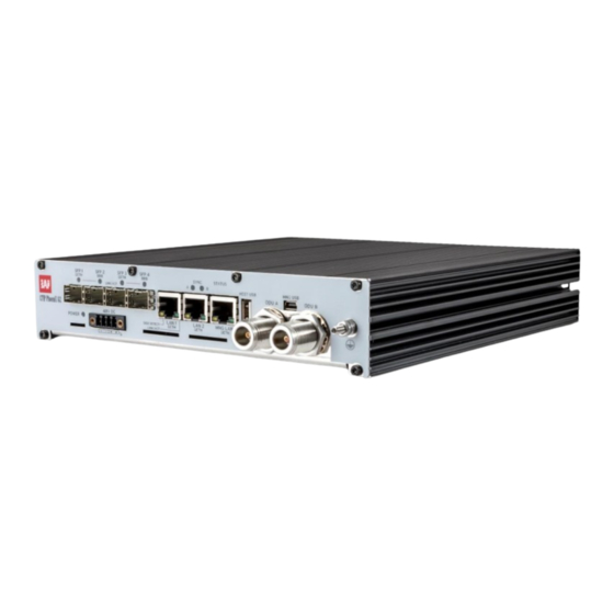
Page 5: Front Panel Ports And Leds
Phoenix G2 IDU Quick Start Guide 3. Front panel ports and LEDs Figure 1: Phoenix G2 front panel DC port – connector for external -48VDC power supply with grounded + pole • 4xSFP ports – SFP slots 1 to 4 for Gigabit Ethernet •... -
Page 6: Basic Interconnection Setup
IDU to the DC power source. Any 2 wire power cable of good quality which fits well in SAF Tehnika’s supplied single block 4 pole “screw on” power connector could be used. - Page 7 Optical cable Optical cable must be used to interconnect PhoeniX G2 IDU and EMM (ASI or E1) modules. Either Single-mode or Multi-mode optical fiber can be used. The same type SFP modules have to be installed in both devices PhoeniX G2 IDU and EMM.
-
Page 8: Labelling
The label contains the following information (see samples in the picture below): Model name. The model name example is: CFIP PhoeniX G2 IDU for PhoeniX G2 Indoor Unit (IDU), CFIP-18-PhoeniX for 18GHz Outdoor Unit (ODU), etc Product Number (EAGXU002, S18RFU05LA): product number contains information of product version (02), in case of ODU - in which frequency band (18) and band side (L, H) the ODU operates. -
Page 9: Connecting Phoenix G2 Idu To Power Source
In case AC/DC Power supply, 48VDC, 80W (EU - P/N I0AB4810, US – P/N I0AB4811, AUS - I0AB4818) provided by SAF Tehnika JSC is used to power up PhoeniX G2 IDU, interconnect IDU and power source through appropriate connectors. Otherwise... - Page 10 (such as an AC outlet third-wire ground). 5. Turn the 48 V DC supply off. 6. Plug the power cable into PhoeniX G2 IDU front panel DC Power connector (DC port). Place the voltmeter probes on the cable connector screw terminal screw heads as described in step 2 above.
-
Page 11: Connecting External Multiplexer Modules (Emm) To Power Source
3 above. Figure 10: Phoenix G2 IDU DC Power Cable Connector of type 2ESDV-04 After successful powering of PhoeniX G2 IDU there are four ways to adjust and read settings and operation parameters of the PhoeniX G2 equipment: ... -
Page 12: Phoenix G2 Installation In The Rack
3 and 4 can be used to connect to EMM module. On EMM module SFP port 1 can be used to connect to Phoenix G2 IDU and SFP port 2 must be used to connect to the next cascaded EMM module. -
Page 13: Accessing The Unit
Figure 13: Dual device installation 5. Accessing the unit 1. Connect your PC to MNG LAN 3 port on PhoeniX G2 IDU with Ethernet cable. 2. Launch your WEB browser and enter PhoeniX G2 IDU’s IP address in the address field. Use default IP address 10.10.10.10. -
Page 14: Configuration
Phoenix G2 IDU Quick Start Guide Figure 14: Login screen 5. Press button The WEB GUI interface requires enabled JavaScript in your browser. There are three access levels available. Default access details for each level are following: ACCESS level LOGIN name... - Page 15 Phoenix G2 IDU Quick Start Guide 2) Step 2 – in web GUI “Config IP” specify IP address/subnet mask and Gateway IP of the IDU and press button. For more details refer to section 6.3 IP address configuration. 3) Step 3 – in web GUI “ConfigSystemDescription” specify Device Name and press button.
-
Page 16: Web Gui Description
Phoenix G2 IDU Quick Start Guide a) Set Bandwidth to required channel bandwidth and press button; b) Set Max RxACM Profile to required modulation and press button; c) Set Tx Frequency to required transmitting frequency and press button; d) Set Tx Power Limit to required transmitter power level and press button;... -
Page 17: Refresh Interval
2. Two levels menu and Login/Logout box; 3. Third level menu; 4. Side bar frames, contains information about local PhoeniX G2 IDU. 5. Information field. 6.1.1 Refresh Interval... -
Page 18: Configuration Boxes
Phoenix G2 IDU Quick Start Guide button else it will not persist through the device reboot; and the white button has only data refreshing option, but such action does not alter the running or stored configuration. Most common button types used in the WEB GUI are following:... -
Page 19: Header And Status Bar
The physically linked RF units are always in the same row. The displayed speed is average maximal throughput per last second. Meaning of the used graphics is described in the following picture: Figure 16: Phoenix G2 IDU web GUI header and status bar SAF Tehnika JSC... -
Page 20: Main Menu
Phoenix G2 IDU Quick Start Guide 6.1.5 Main menu The main menu located on the left side allows user navigation among all major sections of the GUI. The administrative role of the current login and the logout button is displayed above the main menu. The user can expand the menu tree structure either by using the arrows on the left or using double-click on the desired section. -
Page 21: Design And Mode Settings
Figure 17: Phoenix G2 IDU Mode configuration 6.2.1 Description of Design 505 (Single Mount Configuration) This design type should be selected for applications where only one PhoeniX G2 IDU is in use on each side of the link. It supports following Radio Duplex Modes: ... -
Page 22: Description Of Design 511 (Full Protection Configuration)
Split 1+1 - full protection mode which uses one physical channel on each PhoeniX G2 IDU, two IDUs must be used at each side of the link o FD - frequency diversity configuration with frequency separation in both physical channels... -
Page 23: Ip Address Configuration
Navigate to “ConfigIP” in the web GUI menu to configure IP address of the Phoenix G2 IDU. Figure 18: Phoenix G2 IDU IP address configuration Enter the required Device IP / Mask address and Gateway IP address. Example: 192.168.2.92 / 24, where “24” after slash corresponds to the subnet mask 255.255.255.0. -
Page 24: Device Name Configuration
6.5 Modem and Radio configuration Navigate to “ConfigRadio” in the web GUI menu to configure modem and radio parameters. Figure 19: Phoenix G2 IDU modem and radio configuration The ODU must be connected to the IDU when configuring modem and radio settings 6.5.1 Modem settings... -
Page 25: Radio Settings
RF output due to specific tests or troubleshooting process. 6.6 Management access/channel configuration Navigate to “ConfigPortsEthVLAN” in web GUI to access Ethernet port configuration page in order to configure management access type and port grouping. Figure 20: Phoenix G2 IDU ports configuration SAF Tehnika JSC... -
Page 26: Out-Band Management
LAN port which is in the same group with MNG CPU port. The example is given below: Figure 21: Phoenix G2 IDU out-band MNG configuration The example in Figure 21 shows one of grouping configuration options for out-band management. -
Page 27: Alarm Configuration
Phoenix G2 IDU Quick Start Guide Figure 22: Phoenix G2 IDU in-band MNG configuration The example in Figure 22 shows one of grouping configuration options for in-band management. In the example management is accessible via all three LAN ports, and management channel and user traffic will be passed over RF via WANb port. -
Page 28: Configuration Saving
Phoenix G2 IDU Quick Start Guide Figure 23: Phoenix G2 IDU alarm configuration Alarms are divided into two sections: Major - alarms with direct, immediate impact on the link operability Minor - alarms with partial, immediate impact on the link For correct protection role switching, the user have to configure all the Pri/Sec switch alarms appropriately. -
Page 29: Firmware And License Upgrade
“MaintenanceFirmware” in web GUI. It will guide you through the whole firmware upgrade process. If an EMM chain is used, update the EMM chain as well in the same web GUI page. Figure 24: Phoenix G2 IDU firmware upgrade Basically the firmware upgrade can be done in 3 steps: ... - Page 30 Phoenix G2 IDU Quick Start Guide Figure 25: Phoenix G2 IDU license upgrade The license file is activated immediately, but the running configuration is not automatically updated with possible new licensing options or features. Therefore it is recommended to reboot the device after the license upgrade.
Need help?
Do you have a question about the Phoenix G2 IDU and is the answer not in the manual?
Questions and answers