Table of Contents
Advertisement
Advertisement
Table of Contents

Related Manuals for SAF Phoenix G2 IDU


Summary of Contents for SAF Phoenix G2 IDU
- Page 1 User manual Phoenix G2 IDU VER 1.10 FW 0 4 03 _ 0 4...
- Page 2 Proprietary notice The information presented in this guide is the property of SAF Tehnika, JSC. No part of this document may be reproduced or transmitted without proper permission from SAF Tehnika, JSC. The specifications or information contained in this document are subject to change without notice due to continuing introduction of design improvements.
-
Page 3: Table Of Contents
System requirements ....................50 Ethernet management connection configuration ..........50 USB Management connection configuration ............50 Accessing PhoeniX G2 IDU Web GUI ............... 51 Web GUI description ....................52 Button conversion and configuration box description ......... 55 Configuration of basic system parameters ............56 Management channel configuration options ............ - Page 4 Chapter 4: COMMAND LINE INTERFACE ..............110 Connecting to SSH ......................112 Connecting to Telnet .....................113 Chapter 5: EXAMPLES .......................115 Example 1 – Configuration of SFP ports for GE traffic transmission ....115 Example 2 – Basic 1+1 HSB/SD protection scheme ..........118 SAF Tehnika JSC...
- Page 5 Example 15 – 1+1 FD Full protection scheme ............196 Example 16 – VLAN configuration ................202 Appendix A: TECHNICAL SPECIFICATION ..............205 Appendix B: ASI EMM TECHNICAL SPECIFICATION ..........209 Appendix C: E1/T1 EMM TECHNICAL SPECIFICATION ..........210 Appendix D: IRFU TECHNICAL SPECIFICATION ............211 ABBREVIATIONS ........................212 SAF Tehnika JSC...
-
Page 6: Chapter 1: Overview
The primary traffic interface for PhoeniX G2 split mount system is Gigabit Ethernet. As PhoeniX G2 system is capable of providing bit rate of up to 452Mbps, it is a great addition to SAF portfolio. PhoeniX G2 radio and modem performance allows achieving high system capacity by employing 1024-decision states modulation scheme by user’s choice. - Page 7 Phoenix G2 IDU User Manual OVERVIEW For 2.3GHz radio, end-user is responsible for limiting systems E.I.R.P within allowed operational license to be in line with Tx Power plus antenna gain and minus attenuation in cabling between radio and antenna. For example, to assuming the operational license allows 2000W E.I.R.P and radio Tx power is set at 36 dBm and there is 0 dB cable loss between...
-
Page 8: Labelling
Labelling The label contains the following information (see samples in the picture below): Product model name (PhoeniX G2 IDU for PhoeniX G2 Indoor Unit, CFIP-18-PhoeniX for 18GHz Outdoor Unit, etc). Product Number / Model Number (P/N or M/N) (EAGXU002, S18RFU05LA): product/model number contains information about the unit. -
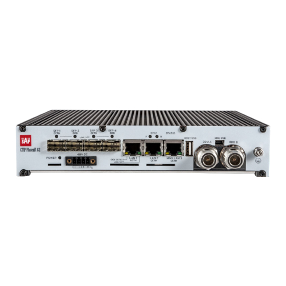
Page 9: Idu Front Panel Interfaces And Leds
Phoenix G2 IDU User Manual OVERVIEW P/N Translation for CFIP PhoeniX G2 ODU: • “S” designates CFIP split mount series product; • “18” designates Frequency range (18 GHz) of the Unit; • “RF” designates standard power radio; • “U” designates unified band ODU operating 7 - 60MHz;... - Page 10 3A). 4-wire DC power connector with screw terminals included. Polarity layout indicated on the front panel. Any 2 wire power cable of good quality which fits well in SAF Tehnika’s supplied 4 pole “screw on” power connector could be used.
-
Page 11: Application Examples
N-type female 50Ω coaxial ports for connecting ODUs. Any type of 50 Ω coaxial cable of good quality can be used to interconnect the Phoenix G2 IDU and ODUs. The cable should be equipped with N–type male connectors on each end. - Page 12 Phoenix G2 IDU User Manual OVERVIEW Figure 1.9 PhoeniX G2 1+0 Repeater configuration PhoeniX G2 1+1 Frequency Diversity (FD): FD protected (1+1) configuration is used with single antenna and OMT (orthomode transducer) or a coupler at each side of the link ...
- Page 13 Phoenix G2 IDU User Manual OVERVIEW Figure 1.11 PhoeniX G2 1+1 SD configuration PhoeniX G2 1+1 Full protection configuration: 1+1 HSB, FD and SD full protection is provided. SD supports only fixed hot- swap role – primary or secondary ...
-
Page 14: Emm Extension Modules Description
Phoenix G2 IDU User Manual OVERVIEW Layer 1Link bonding is supported as aggregation technique Figure 1.13 PhoeniX G2 2+0/2+0 XPIC configurations PhoeniX G2 2+2 FD/2+2 XPIC configurations: 2+2 FD configuration is used to aggregate payload traffic (capacity doubling) using 2 frequency pairs. - Page 15 Phoenix G2 IDU User Manual OVERVIEW the fibre optic (FO) connection to/from the Phoenix G2 IDU. The ASI EMM module features 4 x ASI built-in ports (one BNC per ASI channel) and 2 x SFP 1000Base-SX ports. The compact, simple to configure, and easily scalable design enables cascading with other EMM extension devices (e.g.
- Page 16 EMM module. On EMM module SFP port 1 can be used to connect to Phoenix G2 IDU and SFP port 2 must be used to connect to the next cascaded EMM module. Figure 1.16 Phoenix G2 IDU and ASI EMM module interconnection...
- Page 17 Phoenix G2 IDU User Manual OVERVIEW Application of 1+0 link connection with ASI EMM modules: Figure 1.17 1+0 link with ASI EMM modules Application of 1+1 link connection with ASI EMM modules: Figure 1.18 1+1 link with ASI EMM modules...
- Page 18 Figure 1.19 1+1 full protection link with ASI EMM modules In 1+1 Full protection mode EMM modules can be connected only to SFP3 and SFP4 ports of the Phoenix G2 IDU. SFP1 port is for both Phoenix G2 IDU interconnection and SFP2 port is reserved for 2+2 modes...
- Page 19 Phoenix G2 IDU User Manual OVERVIEW 1+0 retranslation application with ASI EMM modules: Figure 1.20 1+0 retranslation link with ASI EMM modules The retranslation IDU in Figure 1.20 is configured in 1+0 Dual mode. SAF Tehnika JSC...
- Page 20 Phoenix G2 IDU User Manual OVERVIEW 1+0 retranslation application with 2xASI streams ‘Drop’ in the retranslation site. Other 2xASI streams are forwarded to the end-point: Figure 1.21 1+0 retranslation link with ASI stream Drop SAF Tehnika JSC...
-
Page 21: E1/T1 Emm Extension Module
The E1/T1 EMM module multiplexes up to 16 E1/T1 channels into the compact stream which is directed over the fibre optic (FO) connection to/from the Phoenix G2 IDU. The E1/T1 EMM module features 16 x E1/T1 built-in ports (one RJ-45 per e1/t1 channel) and 2 x SFP 1000Base-SX ports. - Page 22 3A). 2-wire DC power connector with screw terminals included. Polarity layout indicated on the front panel. Any 2 wire power cable of good quality which fits well in SAF Tehnika’s supplied 2 pole “screw on” power connector could be used.
- Page 23 Phoenix G2 IDU User Manual OVERVIEW E1/T1 EMM module front panel alarm LED indications: LED name Description Orange – OK, module enabled, proper communication with the IDU Orange blinks – WARNING, module is not enabled in the system or no...
- Page 24 EMM module. On EMM module SFP port 1 can be used to connect to Phoenix G2 IDU and SFP port 2 must be used to connect to the next cascaded EMM module. Figure 1.26 Phoenix G2 IDU and E1/T1 EMM module interconnection Application of 1+0 link connection with E1/T1EMM modules: Figure 1.27 1+0 link with E1/T1 EMM modules...
- Page 25 Phoenix G2 IDU User Manual OVERVIEW Application of 1+1 link connection with E1 EMM modules: Figure 1.28 1+1 link with E1/T1 EMM modules Application of 1+1 full protection link connection with E1/T1 EMM modules: Figure 1.29 1+1 full protection link with E1/T1 EMM modules...
- Page 26 OVERVIEW In 1+1 Full protection mode EMM modules can be connected only to SFP3 and SFP4 ports of the Phoenix G2 IDU. SFP1 port is for both Phoenix G2 IDU interconnection and SFP2 port is reserved for 2+2 modes 1+0 retranslation application with E1/T1 EMM modules: Figure 1.30 1+0 retranslation link with E1/T1 EMM modules...
- Page 27 Phoenix G2 IDU User Manual OVERVIEW 1+0 retranslation application with E1/T1 Add/Drop in the retranslation site: Figure 1.31 1+0 retranslation link with E1/T1 Add/Drop SAF Tehnika JSC...
-
Page 28: Phoenix G2 Odu And Irfu Interfaces And Ports
Phoenix G2 IDU User Manual OVERVIEW Phoenix G2 ODU and IRFU interfaces and ports SP/HP ODU Phoenix G2 Standard Power (SP)/High Power (HP) ODU has following interfaces: Figure 1.32 SP/HP ODU interfaces UBR flange Standard UBR flange for ODU interconnection with antenna. Flange size depends on the frequency used. -
Page 29: Sp/Hp Odu With Saf2 Adaptation Interface
Phoenix G2 IDU User Manual OVERVIEW N-type connector N-type Female connector for ODU interconnection to IDU with coaxial cable Grounding screw Grounding screws should be interconnected with grounding cable and connected to ground circuit SP/HP ODU with SAF2 adaptation interface... -
Page 30: Vhp Odu
Phoenix G2 IDU User Manual OVERVIEW Figure 1.35 Typical RSSI=f(RSL) chart N-type connector N-type Female connector for ODU interconnection to IDU with coaxial cable Grounding screw Grounding screws should be interconnected with grounding cable and connected to ground circuit VHP ODU... -
Page 31: Irfu With Built-In Diplexer
Phoenix G2 IDU User Manual OVERVIEW Twisted polarization flange VHP ODU features twisted polarization flange and resulting signal polarization is determined by interface on antenna/OMT. To change signal polarization, only the antenna interface should be rotated, as radio always remains in vertical position. - Page 32 3A). 2-wire DC power connector with screw terminals included. Polarity layout indicated on the front panel. Any 2 wire power cable of good quality which fits well in SAF Tehnika’s supplied 2 pole “screw on” power connector could be used.
-
Page 33: Irfu Without Built-In Diplexer
3A). 2-wire DC power connector with screw terminals included. Polarity layout indicated on the front panel. Any 2 wire power cable of good quality which fits well in SAF Tehnika’s supplied 2 pole “screw on” power connector could be used. -
Page 34: Ibu Without Active Switch
Phoenix G2 IDU User Manual OVERVIEW Figure 1.41 Typical RSSI=f(RSL) chart IF port SMA IF connector for connection to IDU RX port SMA connector for IRFU Rx interconnection with external branching unit TX port SMA connector for IRFU Tx interconnection with external branching unit... - Page 35 Phoenix G2 IDU User Manual OVERVIEW Figure 1.42 IBU front panel interfaces RX1 and RX2 ports SMA connector for IBU interconnection with corresponding IRFU Rx port TX1 and TX2 ports SMA connector for IBU interconnection with corresponding IRFU Tx port Backpanel of the IBU: Figure 1.43 IBU top-back panel interfaces...
- Page 36 The Figure 1.43 shows the IBU P/N C06U43BSR3M with outgoing CMR137 (UER70) waveguide flange. For other options refer to the IBU product datasheet or SAF representative. Example of IRFU and IBU interconnection using the 1+1 or 2+0 application with single IDU: Figure 1.44 IRFU and IBU interconnection using single IDU...
-
Page 37: Ibu With Active Switch
3A). 2-wire DC power connector with screw terminals included. Polarity layout indicated on the front panel. Any 2 wire power cable of good quality which fits well in SAF Tehnika’s supplied 2 pole “screw on” power connector could be used. - Page 38 Phoenix G2 IDU User Manual OVERVIEW Figure 1.47 IRFU and IBU interconnection using single IDU It is not recommended to use external PSU for powering the IRFU via DC port in 1+1 configuration, as the redundancy functionality may be lost...
- Page 39 Phoenix G2 IDU User Manual OVERVIEW Figure 1.48 IRFU and IBU interconnection using two IDUs SAF Tehnika JSC...
-
Page 40: Chapter 2: Installation
The installation of Phoenix G2 IDU and ODU link involves the following steps: Install the Phoenix G2 IDU in 19” rack: as the IDU is ½ width of the 19” inch rack position, there are two options how to install it in the rack: Option one: Single device installation: attach blank panel and bracket to the IDU (all included in the package). -
Page 41: Attaching Phoenix G2 Odu To Antenna
Ground Phoenix G2 IDU by interconnecting it’s grounding screw with the grounding point of the rack In case if the Phoenix G2 IDU will be used in 1+0 Ch1 mode, connect ODU to the IDU’s IF port ODU A with coaxial cable before turning on the power In case if the Phoenix G2 IDU will be used in 1+0 Ch2 mode, connect ODU to the IDU’s IF... - Page 42 For extra protection from sun radiation it is recommended to install sun shield to cover the radio. In order to attach the SP/HP ODU to SAF non-adapted antenna separated ODU mounting bracket (P/N S0SPKS03) and flexible waveguide/coaxial cable is required...
-
Page 43: Vhp And Sp/Hp Odu With Saf2 Adaptation Interface
Phoenix G2 IDU User Manual INSTALLATION Figure 2.4 SP/HP ODU with mounting bracket For instructions how to connect SP/HP ODU to mounting bracket refer to “SAF mounting bracket installation V1.0” document VHP and SP/HP ODU with SAF2 adaptation interface Tools required: Size 5 Allen wrench, 240mm... - Page 44 Phoenix G2 IDU User Manual INSTALLATION Always this side down 11 GHz VHP ODU, 6 GHz VHP ODU, suited for both V and H polarization suited for both V and H polarization Figure 2.5 VHP ODU flange Examples of VHP ODU polarizations:...
- Page 45 Phoenix G2 IDU User Manual INSTALLATION Examples of SP/HP ODU with SAF2 adaptation interface polarizations: Example of vertical polarization Example of horizontal polarization As both those ODUs have the same SAF2 interface, the steps of ODU interconnection with antenna for both are the same and are given below:...
-
Page 46: Cable Requirements
Phoenix G2 IDU User Manual INSTALLATION Use air level to verify that VHP ODU is properly Final view of assembled VHP ODU 1+0 setup. levelled. Tighten all four fixation clamps properly. Final view of assembled SP/HP ODU with SAF2 Final view of assembled SP/HP ODU with SAF2... - Page 47 IDU to the DC power source. Any 2 wire power cable of good quality which fits well in SAF Tehnika’s supplied single block 4 pole “screw on” power connector could be used. The power connector is 2 pole, type 2ESDV-04P.
-
Page 48: Powering Phoenix G2 Idu/Odu
E1) modules. Either Single-mode or Multi-mode optical fiber can be used. The same type SFP modules have to be installed in both devices PhoeniX G2 IDU and EMM. In order to interconnect two Phoenix G2 IDUs for 1+1 Full redundancy configuration 2.5 Gbps optical cable and SFP modules must be used. -
Page 49: Powering External Multiplexer Modules (Emm)
(such as an AC outlet third-wire ground). 5. Turn the 48 V DC supply off. 6. Plug the power cable into PhoeniX G2 IDU front panel DC Power connector (DC port). Place the voltmeter probes on the cable connector screw terminal screw heads as described in step 2 above. -
Page 50: Chapter 3: Web Gui
WEB GUI Chapter 3: WEB GUI Initial configuration System requirements To access PhoeniX G2 IDU Web GUI you will need a PC with the following system requirements: Operating system Microsoft Windows XP / Vista / 7 / 8/10; ... -
Page 51: Accessing Phoenix G2 Idu Web Gui
Accessing PhoeniX G2 IDU Web GUI 1. Connect your PC to MNG LAN 3 port on PhoeniX G2 IDU with Ethernet patch cable. 2. Launch your Web browser and in address field enter PhoeniX G2 IDU IP address. Default IP address is 10.10.10.10. -
Page 52: Web Gui Description
Phoenix G2 IDU User Manual WEB GUI Depending on your WEB Browser you may be warned that the device has a self-signed certificate and thus it is not secure to connect to it. To avoid this message you have to either setup device certificates or allow an exception for the target IP. - Page 53 Phoenix G2 IDU User Manual WEB GUI Figure 3.5 PhoeniX G2 web GUI Web GUI is divided into 5 sections: Header and status bar The header displays the actual link condition. The RF path diagram varies depending on the used Design and Mode setting. In the Split 511 design, the actual Local Primary unit is displayed in the first header row, the Local Secondary on the second row.
- Page 54 Phoenix G2 IDU User Manual WEB GUI Figure 3.6 PhoeniX G2 web GUI header and status bar Two level menu and Login/Logout box Allows navigating between main pages and sub-pages. The user can expand the menu tree structure either by using the arrows on the left or using double-click on the desired section. The...
-
Page 55: Button Conversion And Configuration Box Description
Phoenix G2 IDU User Manual WEB GUI Time – system time Uptime – time since startup Refresh status – indicates the amount of time until the next GUI refresh. The bar changes its colour to red if the GUI auto-refresh is frozen through the button. -
Page 56: Configuration Of Basic System Parameters
Phoenix G2 IDU User Manual WEB GUI information from the device and renders it on the screen. The colour of configuration value entered in a setting box indicates the status of the following value: black – unmodified value ... - Page 57 Phoenix G2 IDU User Manual WEB GUI Figure 3.8 IP address configuration 3) Step 3 – in web GUI “Config Radio Parameters” set Bandwidth and Max RxACM Profile settings for modem, and Tx Frequency, Tx Power Limit and Tx Mute Config settings for radio Figure 3.9 Modem and Radio parameters configuration...
-
Page 58: Management Channel Configuration Options
Phoenix G2 IDU User Manual WEB GUI 5) Step 5 – save configuration by pressing button. Management channel configuration options There are several options for accessing the remote side management from or via local device: In-Band management User data and management data share the common link capacity and are separated by a VLAN ... - Page 59 Phoenix G2 IDU User Manual WEB GUI b) SSH – this option will add automatic NAT record for accessing the remote IDU’s SSH. The default values are as follows (the IP portion is only an example and depends on actual running IP configuration): 1022 192.168.3.91:22...
-
Page 60: Status
Phoenix G2 IDU User Manual WEB GUI Status Status General Overview It indicates overall system status. Figure 3.11 Status General Overview screen 1) Device IP – IP addresses of devices in the link; 2) Data encryption – encryption status;... -
Page 61: Status General System
Phoenix G2 IDU User Manual WEB GUI 1) Link Status (actual) – actual status of a port as detected by the device (speed, duplex mode, link, administrative down status); 2) Mode – actual port settings (speed/duplex, administrative down); 3) Flow Control – actual duplex flow control mechanism settings;... -
Page 62: Status General License
Phoenix G2 IDU User Manual WEB GUI Figure 3.13 Status General System screen 1) Fan Function – shows the actual fan configuration status and actual spinning speed; 2) Modem Unit Temp – temperature of the modem part; 3) IF Rx Level @140 Mhz – the IF signal strength detected on thecable input of the modem part;... -
Page 63: Status Events Actual
Phoenix G2 IDU User Manual WEB GUI Figure 3.14 Status General License screen Status Events Actual This section contains the list of alarms which are active at the current moment. It should be empty when the equipment works properly and without alarms. -
Page 64: Status Events All
Phoenix G2 IDU User Manual WEB GUI Figure 3.16 “Status Events Historical” page Status Events All This section contains the conjunction of both Actual and Historical alarms. Figure 3.17 “Status Events All” page SAF Tehnika JSC... -
Page 65: Status Counters Modem
Phoenix G2 IDU User Manual WEB GUI Status Counters Modem This section displays basic modem performance counters and built-in Bit Error Rate (BER) counters. For BER counter only unassigned capacity will be used (Refer to Config Ports ... -
Page 66: Status Counters Traffic
Phoenix G2 IDU User Manual WEB GUI 12) Actual Tx Speed – shows reserved transmission speed for BER tester. This value roughly equals to half of the unassigned capacity which is used for the BER tester 13) TX Pattern – shows transmission pattern for BER tester frames 14) RX Pattern –... -
Page 67: Status Counters Management
Phoenix G2 IDU User Manual WEB GUI Figure 3.19 “Status Counters Traffic” page Status Counters Management This section displays IP statistics of IDU’s interfaces. SAF Tehnika JSC... - Page 68 Phoenix G2 IDU User Manual WEB GUI Figure 3.20 “Status Counters Management” page 1) eth0 – Ethernet port of MNG CPU with its own MAC address and all the standard features of Ethernet interface. Device/Fallback addresses and appropriate subnet masks are assigned to this interface.
- Page 69 Phoenix G2 IDU User Manual WEB GUI Figure 3.21 “Status Trends Actual” page Status Trends Historical The graph in this section displays the selected values in dependence on time. If the connection with remote side is established, the values from the remote unit are will be displayed.
- Page 70 Phoenix G2 IDU User Manual WEB GUI Figure 3.22 “Status Trends Historical” page Status Inventory This section shows the device hardware/software information as well as radio part information. Figure 3.23a “Status Inventory” page If any of EMM modules are connected to the IDU and enabled, additional EMM information will...
- Page 71 Phoenix G2 IDU User Manual WEB GUI Figure 3.23b “Status Inventory” page Config Config System Mode In this section the user can select specific Design Type which specifies the main function of the system/link. Figure 3.24 “Config ...
- Page 72 It is recommended not to use ACM when 1+1 SD or 1+1 HSB/SD modes are used with separated antennas in each side of the link. In some circumstances the ACM in combination with 1+1 SD mode might not work properly. For more details please refer to SAF technical support at techsupport@saftehnika.com...
Need help?
Do you have a question about the Phoenix G2 IDU and is the answer not in the manual?
Questions and answers