Advertisement
Quick Links
Installation Instructions
Original Instructions
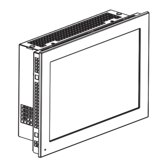
OptixPanel Compact Operator Panels
Bulletin 2800C
Equipment with the UL/cUL mark complies with the requirements of UL 61010-1, UL 61010-2-201, CSA C22.2 No. 61010-1, and CSA C22.2 No. 61010-
2-201. Copies of the certificate of compliance are available at rok.auto/certifications.
ATTENTION: This equipment is intended for use in a Pollution Degree 2 industrial environment, in overvoltage Category II applications (as defined in
IEC 60664-1), at altitudes up to 2000 m (6561 ft) without derating.
This equipment is considered Group 1, Class A industrial equipment according to EN 61326-1. Without appropriate precautions, there can be potential
difficulties with electromagnetic compatibility in other environments caused by conducted as well as radiated disturbance.
In addition to this publication, see the following:
• Industrial Automation Wiring and Grounding Guidelines, publication 1770-4.1, for more installation requirements.
• UL 50, UL 50E, CSA C22.2, No. 94.1, and CSA C22.2, No. 94.2, as applicable, for explanations of the degrees of protection provided by enclosures.
European Union Directive and UKCA Compliance
This equipment meets the European Union Directive and UK requirements when installed within the European Union, UK, or EEA regions and have the CE or UKCA marking. A
copy of the declaration of the conformity is available at rok.auto/certifications.
ATTENTION: This operator panel is intended to operate in an industrial or control room environment, which uses some form of power isolation from the
public low-voltage mains. Some computer configurations cannot comply with the EN 61000-3-2 Harmonic Emissions standard as specified by the EMC
Directive of the European Union. Obtain permission from the local power authority before you connect any computer configuration that draws more
than 75 W of AC power directly from the public mains. All I/O cables are rated for indoor use only.
Installation Guidelines
Follow these guidelines to make sure that your OptixPanel™ operator panel provides service with excellent reliability.
•
When choosing the installation site, consider the following:
- The site must have sufficient power.
- The site must be indoors and non-hazardous.
- The site must not expose the computer to direct sunlight.
•
The operator panel can operate in the following environmental conditions:
- Operating temperature: 0...50 °C (32...122 °F).
- Storage temperature: -20...+60 °C (-4...140 °F).
Operation/storage relative humidity (RH) noncondensing: 20%...90%.
Follow these requirements to mount the operator panel.
•
Choose a suitable mounting height.
•
To help prevent overheating and to provide access to the I/O ports for cable connections, mount the operator panel with
the following minimum clearances from all four sides of the outer frame and back of the operator panel chassis:
- X direction ≥ 50 mm (1.96 in.)
- Y direction ≥ 100 mm (3.93 in.)
- Z direction ≥ 50 mm (1.96 in.)
•
For optimal performance, mount the operator panel in the horizontal orientation and vertical (upright) position, so the I/O
ports face down.
IMPORTANT
The vertical position can be tilted up to 20° forward or 20° backward from the upright position. However, this acceptable tilt angle range decreases
the maximum operating air temperature to 45 °C (113 °F).
Installation min. clearance
Y
X
Z
X
Y
Installation max. tilt
°
0
°
°
-20
-20
Advertisement

Related Manuals for Rockwell Automation Allen-Bradley OptixPanel

Summary of Contents for Rockwell Automation Allen-Bradley OptixPanel
- Page 1 Installation Instructions Original Instructions OptixPanel Compact Operator Panels Bulletin 2800C Equipment with the UL/cUL mark complies with the requirements of UL 61010-1, UL 61010-2-201, CSA C22.2 No. 61010-1, and CSA C22.2 No. 61010- 2-201. Copies of the certificate of compliance are available at rok.auto/certifications. ATTENTION: This equipment is intended for use in a Pollution Degree 2 industrial environment, in overvoltage Category II applications (as defined in IEC 60664-1), at altitudes up to 2000 m (6561 ft) without derating.
- Page 2 (C). Slide the mounting clips into the holes on all four sides of the operator panel and repeat the procedure in step 7 through step 9 for all clips. Rockwell Automation Publication 2800C-IN001B-EN-P - June 2023...
- Page 3 Figure 1 - Mounting clips tighten and torque sequence by display size ATTENTION: Tighten the mounting clips to the specified torque to provide a proper seal and to help prevent product damage. Rockwell Automation assumes no responsibility for water or chemical damage to the computer or other equipment within the enclosure because of improper installation.
- Page 4 Insert the cable tie (9) through the slots of the terminal block (11) connector clamp [step (A)]. Slide the connector half with the attached tie onto the end of the DC terminal block [step (B)]. Tighten the tie and remove the excess part [step (C)]. Rockwell Automation Publication 2800C-IN001B-EN-P - June 2023...
-
Page 5: Additional Resources
On OptixPanel Compact systems front LED (b) is present only on 7.0 in. size. Additional Resources These documents contain additional information concerning related products from Rockwell Automation. You can view or download publications at rok.auto/literature. Resource Description OptixPanel Compact User Manual, publication 2800C-UM001 Provides details on how to install, configure, operate, and troubleshoot the OptixPanel operator panels. -
Page 6: Rockwell Automation Support
Rockwell Otomasyon Ticaret A.Ş. Kar Plaza İş Merkezi E Blok Kat:6 34752 İçerenköy, İstanbul, Tel: +90 (216) 5698400 EEE Yönetmeliğine Uygundur *PN-696497* Allen-Bradley, expanding human possibility, OptixPanel, and Rockwell Automation are trademarks of Rockwell Automation, Inc. PN-696497 Trademarks not belonging to Rockwell Automation are property of their respective companies.