Scotsman MDT6N90 Service Manual
Scotsman mdt6n90 ice dispenser: user guide
Hide thumbs
Also See for MDT6N90:
- Datasheet (2 pages) ,
- Installation and user manual (16 pages) ,
- Service manual (29 pages)
Table of Contents
Advertisement
Quick Links
INTRODUCTION
To the owner or user: The service manual you are
reading is intended to provide you, and the
maintenance or service technician with the
information needed to install, start up, clean,
maintain, and service this ice maker-dispenser.
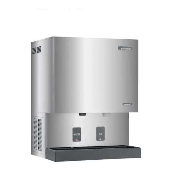
The MDT6 is a combination nugget ice maker and
countertop dispenser. A water station is standard.
FOR THE INSTALLER: Specifications · · · · · · · · · · · · · · · · · · · · · · · · · · · · · · Page 2
FOR THE INSTALLER · · · · · · · · · · · · · · · · · · · · · · · · · · · · · · · · · · · · · · Page 3
FOR THE PLUMBER · · · · · · · · · · · · · · · · · · · · · · · · · · · · · · · · · · · · · · · Page 4
FOR THE ELECTRICIAN · · · · · · · · · · · · · · · · · · · · · · · · · · · · · · · · · · · · · Page 5
FOR THE INSTALLER: Final Check List · · · · · · · · · · · · · · · · · · · · · · · · · · · · · Page 6
INITIAL START UP · · · · · · · · · · · · · · · · · · · · · · · · · · · · · · · · · · · · · · · · Page 7
COMPONENT DESCRIPTION · · · · · · · · · · · · · · · · · · · · · · · · · · · · · · · · · · Page 8
COMPONENT DESCRIPTION · · · · · · · · · · · · · · · · · · · · · · · · · · · · · · · · · · Page 9
CONTROL BOX
· · · · · · · · · · · · · · · · · · · · · · · · · · · · · · · · · · · · · · · · · Page 10
ELECTRICAL SEQUENCE · · · · · · · · · · · · · · · · · · · · · · · · · · · · · · · · · · · · Page 11
OPERATION: Water · · · · · · · · · · · · · · · · · · · · · · · · · · · · · · · · · · · · · · · Page 12
OPERATION: Refrigeration · · · · · · · · · · · · · · · · · · · · · · · · · · · · · · · · · · · · Page 13
OPERATION: Ice Vending · · · · · · · · · · · · · · · · · · · · · · · · · · · · · · · · · · · · Page 14
DISPENSE AREA SANITATION · · · · · · · · · · · · · · · · · · · · · · · · · · · · · · · · · Page 15
CLEANING and SANITIZING · · · · · · · · · · · · · · · · · · · · · · · · · · · · · · · · · · · Page 16
SENSOR MAINTENANCE · · · · · · · · · · · · · · · · · · · · · · · · · · · · · · · · · · · · Page 17
BEARING MAINTENANCE · · · · · · · · · · · · · · · · · · · · · · · · · · · · · · · · · · · · Page 18
AUGER MAINTENANCE · · · · · · · · · · · · · · · · · · · · · · · · · · · · · · · · · · · · · Page 19
SERVICE DIAGNOSIS · · · · · · · · · · · · · · · · · · · · · · · · · · · · · · · · · · · · · · Page 20
CONTROL SYSTEM DIAGNOSTICS
REMOVAL AND REPLACEMENT · · · · · · · · · · · · · · · · · · · · · · · · · · · · · · · · Page 22
REMOVAL AND REPLACEMENT: Bearing And Breaker · · · · · · · · · · · · · · · · · · · · Page 23
REMOVAL AND REPLACEMENT · · · · · · · · · · · · · · · · · · · · · · · · · · · · · · · · Page 24
REMOVAL AND REPLACEMENT: Water Seal · · · · · · · · · · · · · · · · · · · · · · · · · · Page 25
REMOVAL AND REPLACEMENT · · · · · · · · · · · · · · · · · · · · · · · · · · · · · · · · Page 26
TO REMOVE AND REPAIR THE GEARMOTOR ASSEMBLY · · · · · · · · · · · · · · · · · · Page 27
REFRIGERATION SERVICE · · · · · · · · · · · · · · · · · · · · · · · · · · · · · · · · · · · Page 28
This manual was printed on recycled paper.
Keep it for future reference.
The ice making section is equipped with the
following features: electronic controls for bin level
and low water; thermostatic expansion valve; front
service for most components; and R-404A
refrigerant. The ice dispensing section is a
seamless plastic storage bin, with a stainless steel
ice agitator at the bottom to sweep the ice into the
dispensing chute.
Table of Contents
· · · · · · · · · · · · · · · · · · · · · · · · · · · · · · Page 21
May 2001
Page 1
Note this symbol when it appears.
It marks a possible hazard.
MDT6N90
Advertisement
Table of Contents

Related Manuals for Scotsman MDT6N90


Summary of Contents for Scotsman MDT6N90
- Page 1 INTRODUCTION To the owner or user: The service manual you are reading is intended to provide you, and the maintenance or service technician with the information needed to install, start up, clean, maintain, and service this ice maker-dispenser. The MDT6 is a combination nugget ice maker and countertop dispenser.
-
Page 2: For The Installer: Specifications
*Minimum circuit ampacity is used to determine wire size and type per National Electric Code. Options: Machine stand DMS31. Portion control kit KPC-MDT. Scotsman assumes no liability or responsibility of any kind for products manufactured by Scotsman that have been altered in any way, including the use of any parts and/or other components not specifically approved by Scotsman. -
Page 3: For The Installer
Counter Top or Machine Stand Installation The base of the icemaker-dispenser must be sealed to the object it rests upon. Food grade silastic sealant such as Scotsman part number 19-0529-01 is recommended. Place a bead of the sealant on the machine stand or counter top to match the outside edge of the cabinet base and sink. -
Page 4: For The Plumber
MDT6N90 FOR THE PLUMBER CONFORM TO ALL APPLICABLE CODES Water Inlet Air Cooled Models: Connect a clean, potable and cold water supply to the ” male flare at the back of the cabinet. Install a hand valve near the machine to control the water supply. Use ”... -
Page 5: For The Electrician
MDT6N90 FOR THE ELECTRICIAN CONFORM TO ALL APPLICABLE CODES Connect the electrical power supply for the unit to the wires in the junction box at the rear of the machine. Check the nameplate (located on the back panel) for the voltage requirements, and for the minimum circuit ampacity. -
Page 6: For The Installer: Final Check List
MDT6N90 FOR THE INSTALLER: Final Check List 1. Is the icemaker-dispenser installed ELECTRICAL? indoors, in a location where the air and LEVELED? water temperatures are controlled, and where they do not go beyond design limitations? 2. is there an electrical service... -
Page 7: Initial Start-Up
9. Give the owner/user the service manual, instruct him/her in the operation and maintenance requirements of the unit. Make sure they know who to call for service. 10. Fill out the Customer Evaluation and warranty Registration form, and mail it in to Scotsman. May 2001 Page 7... -
Page 8: Component Description
COMPONENT DESCRIPTION RESERVOIR ICE LEVEL SENSOR EVAPORATOR DRAIN TUBE Control Box: Contains the electrical controls that operate the machine. High Pressure Cut Out Switch: An automatic reset switch sensing the high side refrigeration pressure. It is set to shut the machine off if the discharge pressure should ever exceed 450 psig. -
Page 9: Water Seal
COMPONENT DESCRIPTION Evaporator: A refrigerated vertical tube filled with water and containing a water seal and auger. Auger: A solid stainless steel double spiral auger, it pushes the ice crystals up to the top of the evaporator. Water Seal: A two part “face” seal, the top half rotating with the auger, the bottom half stationary, the sealing action being where the two seal “faces”... -
Page 10: Control Box
CONTROL BOX Circuit Board: The circuit board receives input signals from several sensors and translates them to control the electrical power supply to the various loads. The sensors include: · Touch Free ice or water. · Ice level in the bin. ·... -
Page 11: Electrical Sequence
ELECTRICAL SEQUENCE Refer the wiring diagram as needed. The “Power” light on the board glows whenever there is power to the machine (and the master switch is ON). If the machine is switched off at the master switch, but is otherwise ready to go, switching the master switch to ON does the following: ·... -
Page 12: Operation: Water
OPERATION: Water Water enters the machine through the 3/8" male flare at the rear of the cabinet, goes to the water reservoir which it enters through the float valve. The water then goes out the bottom of the reservoir tank to the bottom of the evaporator. Reservoir overflow, evaporator condensation and water in the sink are all routed to the drain. -
Page 13: Operation: Refrigeration
OPERATION: Refrigeration Beginning at the compressor, the refrigerant is compressed into a high temperature gas. The discharge line directs this gas to the condenser. At the condenser (air or water cooled) the gas is cooled by either air or water and it then condenses into a liquid. -
Page 14: Operation: Ice Vending
MDT6N90 OPERATION: Ice Vending When the ice dispensing sensor detects a container in front of it, the control board connects an electrical circuit to the ice chute door solenoid causing the ice chute door to open. At the same time power is connected to the agitator drive motor. -
Page 15: Dispense Area Sanitation
The dispense area; spouts, sink, grill and splash panel will need periodic cleaning and maintenance. 1. The ice chute may be pulled down to remove it from the ice dispenser. Wash and sanitize it. 2. The sink grill may be removed for washing and sanitizing. -
Page 16: Cleaning And Sanitizing
Return the drain tube to its normal upright position and replace the end cap. 7. Prepare the cleaning solution: Mix eight ounces of Scotsman Ice Machine Cleaner with three quarts of hot water. The water should be between 90-115 degrees F. -
Page 17: Sensor Maintenance
SENSOR MAINTENANCE 1. The ice machine senses water level by a probe located in the water reservoir. At least twice a year, the probe should be removed from the reservoir, and the tip wiped clean of mineral build-up. SLIDE SENSORS UP TO REMOVE 2. -
Page 18: Bearing Maintenance
If the bearing only needs grease, inject grease into the bearing using Scotsman grease needle pn Breaker 02-3559-01 and Scotsman bearing grease Cover cartridge, pn A36808-001. -
Page 19: Auger Maintenance
AUGER MAINTENANCE In some areas, the water supply to the ice maker will contain a high concentration of minerals, and that will result in an evaporator and auger becoming coated with these minerals, requiring a more frequent removal than twice per year. If in doubt about the condition of the evaporator and auger, the auger can be removed so the parts can be inspected. -
Page 20: Service Diagnosis
SERVICE DIAGNOSIS Symptom No ice is made, nothing operates No ice, auger motor is turning Unit makes ice, but very slowly. Possible Cause Unit off due to no power Unit off due to master switch in OFF position. Unit off due to low water level. Unit off due to ice level sensors (photo-electric eyes) blocked. -
Page 21: Control System Diagnostics
CONTROL SYSTEM DIAGNOSTICS The control system consists of: · Control Board · Water Sensor · Ice Sensors · Vending Sensors Explanation of Indicator Light On at all times when the master switch is ON and machine is connected to electrical power. On when ice level is low (unit making ice). -
Page 22: Removal And Replacement
REMOVAL AND REPLACEMENT WATER RESERVOIR 1. Shut off the water supply to the icemaker. 2. Remove front panel and reservoir cover. 3. To remove float only, pry the mounting flanges apart enough to lift one float pivot pin out of the flange hole, and pull float up and out of the reservoir. -
Page 23: Removal And Replacement: Bearing And Breaker
7. Reverse to reassemble: specific tools and materials are required to install properly. a. Add food grade grease such as Scotsman part number 19-0569-01 to the seal area before installing on the auger. b. Check the seal to shaft areas for cuts, or rough spots: none are permitted. -
Page 24: Sharp Edges
REMOVAL AND REPLACEMENT To Remove the Auger: Turn off the water to the machine, and unclip the evaporator drain hose, pull it down and drain the evaporator into the bin or a container. Moving Parts Hazard. Disconnect electrical power to the icemaker - dispenser before beginning. -
Page 25: Removal And Replacement: Water Seal
4. Place a small bead of food grade silastic sealant (such as 732 RTV or Scotsman part number 19-0529-01) on the area of the auger where the water seal is to be mounted. - Page 26 REMOVAL AND REPLACEMENT To Replace the Evaporator: (Assuming all the steps for removal of the thrust bearing, breaker, auger, and water seal have been performed.) 1. Recover the refrigerant from the ice maker. 2. Unsweat the refrigerant connections: a) At the thermostatic expansion valve outlet. Heat sink the TXV body when unsweating or resweating the adjacent tubing.
-
Page 27: To Remove And Repair The Gearmotor Assembly
TO REMOVE AND REPAIR THE GEARMOTOR ASSEMBLY (Assuming that the procedures through removal of the water seal have been performed.) 1. Remove the electrical wires from the gear drive motor. Electrical Shock Hazard. Disconnect electrical power to the icemaker - dispenser before beginning. -
Page 28: Refrigeration Service
REFRIGERATION SERVICE General: This ice machine uses R-404A refrigerant and polyolester oil. Do NOT use mineral oil in this refrigeration system. · When the system is serviced, a special liquid line drier is required. It is included with replacement compressors. ·...
Need help?
Do you have a question about the MDT6N90 and is the answer not in the manual?
Questions and answers