Table of Contents
Advertisement
INTRODUCTION
To the owner or user: The service manual you are
reading is intended to provide you, and the
maintenance or service technician with the
information needed to install, start up, clean,
maintain, and service this ice maker-dispenser.
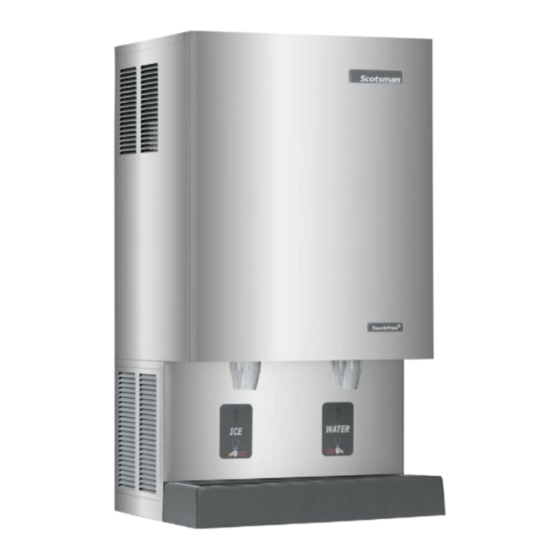
The machine is a combination nugget ice maker
and countertop dispenser, with the option of wall
mounting.
FOR THE INSTALLER: Specifications· · · · · · · · · · · · · · · · · · · · · · · · · · · · · · · · · · · · Page 2
FOR THE INSTALLER: Environmental Limitations · · · · · · · · · · · · · · · · · · · · · · · · · · · · · Page 3
FOR THE INSTALLER· · · · · · · · · · · · · · · · · · · · · · · · · · · · · · · · · · · · · · · · · · · · Page 4
FOR THE INSTALLER: Wall Mount Kit · · · · · · · · · · · · · · · · · · · · · · · · · · · · · · · · · · · Page 5
FOR THE PLUMBER · · · · · · · · · · · · · · · · · · · · · · · · · · · · · · · · · · · · · · · · · · · · Page 6
FOR THE ELECTRICIAN · · · · · · · · · · · · · · · · · · · · · · · · · · · · · · · · · · · · · · · · · · Page 7
FOR THE INSTALLER: Final Check List · · · · · · · · · · · · · · · · · · · · · · · · · · · · · · · · · · Page 8
INITIAL START UP · · · · · · · · · · · · · · · · · · · · · · · · · · · · · · · · · · · · · · · · · · · · · Page 9
COMPONENT DESCRIPTION · · · · · · · · · · · · · · · · · · · · · · · · · · · · · · · · · · · · · · · Page 10
COMPONENT DESCRIPTION · · · · · · · · · · · · · · · · · · · · · · · · · · · · · · · · · · · · · · · Page 11
COMPONENT DESCRIPTION: Control Box · · · · · · · · · · · · · · · · · · · · · · · · · · · · · · · · Page 12
ELECTRICAL SEQUENCE · · · · · · · · · · · · · · · · · · · · · · · · · · · · · · · · · · · · · · · · · Page 13
OPERATION: Water · · · · · · · · · · · · · · · · · · · · · · · · · · · · · · · · · · · · · · · · · · · · · Page 14
OPERATION: Refrigeration · · · · · · · · · · · · · · · · · · · · · · · · · · · · · · · · · · · · · · · · · Page 15
OPERATION: Ice Vending · · · · · · · · · · · · · · · · · · · · · · · · · · · · · · · · · · · · · · · · · · Page 16
DISPENSE AREA SANITATION· · · · · · · · · · · · · · · · · · · · · · · · · · · · · · · · · · · · · · · Page 17
CLEANING and SANITIZING · · · · · · · · · · · · · · · · · · · · · · · · · · · · · · · · · · · · · · · · Page 18
MAINTENANCE AND CLEANING· · · · · · · · · · · · · · · · · · · · · · · · · · · · · · · · · · · · · · Page 19
SERVICE DIAGNOSIS · · · · · · · · · · · · · · · · · · · · · · · · · · · · · · · · · · · · · · · · · · · Page 21
SERVICE DIAGNOSIS: Circuit Board · · · · · · · · · · · · · · · · · · · · · · · · · · · · · · · · · · · · Page 23
REMOVAL AND REPLACEMENT · · · · · · · · · · · · · · · · · · · · · · · · · · · · · · · · · · · · · · Page 24
REMOVAL AND REPLACEMENT: Bearing And Breaker · · · · · · · · · · · · · · · · · · · · · · · · · · Page 25
REMOVAL AND REPLACEMENT: Water Seal · · · · · · · · · · · · · · · · · · · · · · · · · · · · · · · Page 27
TO REMOVE AND REPAIR THE GEARMOTOR ASSEMBLY · · · · · · · · · · · · · · · · · · · · · · · Page 29
REFRIGERATION SERVICE: R-404A (HP62) · · · · · · · · · · · · · · · · · · · · · · · · · · · · · · · Page 30
REFRIGERATION SERVICE · · · · · · · · · · · · · · · · · · · · · · · · · · · · · · · · · · · · · · · · Page 31
CIRCUIT BOARD SERVICE· · · · · · · · · · · · · · · · · · · · · · · · · · · · · · · · · · · · · · · · · Page 32
LIQUID CHARGING
· · · · · · · · · · · · · · · · · · · · · · · · · · · · · · · · · · · · · · · · · · · · Page 32
Parts Lists and Wiring Diagrams are printed on
yellow paper in the center of this manual.
This manual was printed on recycled paper.
Keep it for future reference.
MDT5N25 & MDT5N40
The ice making section is equipped with the
following features: electronic controls for bin level
and low water; thermostatic expansion valve; front
service for most components; and R-404A
refrigerant. The ice dispensing section is a
seamless plastic storage bin, with a stainless steel
rotating vane to sweep the ice into the dispensing
chute.
Table of Contents
Note this symbol when it appears.
May 2001
Page 1
It marks a possible hazard.
Advertisement
Table of Contents

Related Manuals for Scotsman MDT5N40A-1B


Summary of Contents for Scotsman MDT5N40A-1B
- Page 1 MDT5N25 & MDT5N40 INTRODUCTION To the owner or user: The service manual you are The ice making section is equipped with the reading is intended to provide you, and the following features: electronic controls for bin level maintenance or service technician with the and low water;...
-
Page 2: For The Installer: Specifications
115/60/1 Water 17 17.8 MDT5N25A-1J 41 x 26 x 22.5 115/60/1 Air 19.3 MDT5N25W-1J 41 x 26 x 22.5 115/60/1 Water 17 17.8 MDT5N40A-1B 48.5 x 26 x 22.5 115/60/1 Air 19.3 MDT5N40W-1A same 115/60/1 Water 18 17.8 MDT5N40W-1B same 115/60/1 Water 17 17.8... - Page 3 CEILING and performance. They meet or exceed the CUT AWAY standards of UL and NSF. Scotsman assumes no liability or responsibility of any kind for products manufactured by Scotsman SPACE that have been altered in any way, including the ABOVE...
-
Page 4: For The Installer
Counter Top or Machine Stand Installation The base of the icemaker-dispenser must be sealed to the object it rests upon. Food grade silastic sealant such as Scotsman part number 19-0529-01 is recommended. Place a bead of the sealant on the machine stand... -
Page 5: For The Installer: Wall Mount Kit
MDT5N25 & MDT5N40 FOR THE INSTALLER: Wall Mount Kit CAUTION It is recommended that the wall mounting installation be done by an experienced contractor. The weight of the machine when in use may exceed 350 pounds. The unit should be mounted on a solid, rigid wall with proper fasteners for that type of wall and of adequate strength to support the weight of the machine when in use. -
Page 6: For The Plumber
MDT5N25 & MDT5N40 FOR THE PLUMBER CONFORM TO ALL APPLICABLE CODES Water Inlet Air Cooled Models: The recommended water supply is clean, cold water. Use 3/8" O.D. copper tubing, connect to the 3/8" male flare at the back of the cabinet. Install a hand valve near the machine to control the water supply. -
Page 7: For The Electrician
MDT5N25 & MDT5N40 FOR THE ELECTRICIAN CONFORM TO ALL APPLICABLE CODES The electrical power to the unit is supplied through the junction box at the INDIVIDUAL CIRCUIT rear of the machine. FOR ICE DISPENSER Check the nameplate (located on the back panel) for the voltage requirements, and for the minimum circuit ampacity. -
Page 8: For The Installer: Final Check List
MDT5N25 & MDT5N40 FOR THE INSTALLER: Final Check List 1. Is the icemaker-dispenser installed indoors, in a BACK VIEW OF COMPLETED INSTALLATION location where the air and water temperatures are controlled, and where they do not go beyond ELECTRICAL? design limitations? 2. -
Page 9: Initial Start-Up
10. Fill out the Customer Evaluation and Warranty Registration form, and mail it in to Scotsman. 5. The unit should soon be making ice. If desired, the low side pressure may be checked: it should be 38 PSIG + or - 2 PSIG. -
Page 10: Component Description
MDT5N25 & MDT5N40 COMPONENT DESCRIPTION High Pressure Cut Out Switch: A manual reset switch sensing the high side refrigeration pressure. It is set to shut the machine off if the discharge pressure should ever exceed 450 psig. Evaporator: A vertical stainless steel tube, refrigerated, and water filled. -
Page 11: Water Seal
MDT5N25 & MDT5N40 COMPONENT DESCRIPTION Evaporator: A refrigerated vertical tube filled with Motor: A split phase motor that drives the gear water and containing a water seal and auger. reducer. Auger: A solid stainless steel double spiral auger, Thrust Bearing: As the ice is pushed up the it pushes the ice crystals up to the top of the evaporator, the auger is thrust down, and pressure evaporator. -
Page 12: Component Description: Control Box
MDT5N25 & MDT5N40 COMPONENT DESCRIPTION: Control Box Circuit Board: The circuit board receives input signals from several START sensors and translates them to CAPACITOR control the electrical power supply to the various loads. The sensors include: · Touch Free ice or water. ·... -
Page 13: Electrical Sequence
MDT5N25 & MDT5N40 ELECTRICAL SEQUENCE Refer the wiring diagram as needed. The “Power” light on the board glows whenever After a 6 minute delay, If the ice level sensor is there is power to the machine (and the master clear (bin empty) for more than 15 seconds, the switch is ON). -
Page 14: Operation: Water
MDT5N25 & MDT5N40 OPERATION: Water Water enters the machine through the 3/8" male flare at the rear of the cabinet, goes to a strainer and then to the water reservoir which it enters through the float valve. The water then goes out the bottom of the reservoir tank to the bottom of the evaporator. - Page 15 MDT5N25 & MDT5N40 OPERATION: Refrigeration Beginning at the compressor, the refrigerant is At the evaporator, the refrigerant enters an area of compressed into a high temperature gas. The relatively low pressure, where it can easily “boil off” discharge line directs this gas to the condenser. At or evaporate.
-
Page 16: Operation: Ice Vending
MDT5N25 & MDT5N40 OPERATION: Ice Vending Dispensing takes place when the Touch Free sensor’s infrared beam bounces back to the sensor from a container placed directly in front of ICE DISPENSING VANE If the container is in front of the Touch Free sensor on the left side, the ice dispensing vane will rotate and sweep ice over the ice... -
Page 17: Dispense Area Sanitation
MDT5N25 & MDT5N40 DISPENSE AREA SANITATION The dispense area; spouts, sink, grill and splash panel will need periodic cleaning and maintenance. 1. The ice chute may be pulled down to remove it from the ice dispenser. Wash and sanitize it. 2. -
Page 18: Cleaning And Sanitizing
MDT5N25 & MDT5N40 CLEANING and SANITIZING A Scotsman Ice System represents a sizable investment of time and money in any company’s business. In order to receive the best return for that investment, it MUST receive periodic maintenance. It is the USER’S RESPONSIBILITY to see that the unit is properly maintained. It is always preferable, and less costly in the long run, to avoid possible down time by keeping it clean;... -
Page 19: Maintenance And Cleaning
MDT5N25 & MDT5N40 MAINTENANCE AND CLEANING Slide UP To Remove Moving Parts Hazard. Disconnect electrical power to the icemaker - dispenser before Reservoir beginning. 1. Air Cooled Models: Check the air cooled condenser for lint, dirt or grease build-up. Clean with vacuum or soft brush until light can be seen thru the fins. - Page 20 MDT5N25 & MDT5N40 MAINTENANCE AND CLEANING In some areas, the water supply to the ice maker ALLEN will contain a high concentration of minerals, and HEAD that will result in an evaporator and auger SCREWS becoming coated with these minerals, requiring a more frequent removal than twice per year.
-
Page 21: Service Diagnosis
MDT5N25 & MDT5N40 SERVICE DIAGNOSIS Symptom Possible Cause Probable Correction No ice made, nothing operates Unit off due to no power Restore power Unit off due to master switch in Switch master switch to ON OFF position Unit off due to low water level Check water supply, filter, strainer, float valve. - Page 22 Makes ice, but with excessive Mineral scale on auger or Clean ice making system with noise evaporator Scotsman Ice machine cleaner Dry top bearing Check top bearing for proper lubrication Dry auger drive gear motor Check auger drive for proper...
-
Page 23: Service Diagnosis: Circuit Board
MDT5N25 & MDT5N40 SERVICE DIAGNOSIS: Circuit Board Explanation of Indicator Light Position On Name and Meaning of Board Light or Reset On at all times when the master switch is ON and machine is Power, connected to electrical power. ON = Normal On when ice level is low (unit making ice). - Page 24 Scotsman MTD3, MDT4, MDT5, MDT6 Service Diagnostic - Touch Free and Control System The MDT controller operates the refrigeration and dispensing systems. The on/off of the ice making system is determined by infrared sensors. Ice or water dispensing is also determined by infrared sensors.
-
Page 25: Removal And Replacement
MDT5N25 & MDT5N40 REMOVAL AND REPLACEMENT WATER RESERVOIR BIN CONTROLS (Ice Level Sensors) 1. Shut off the water supply to the icemaker. 1. Disconnect electrical power. 2. Remove front panel and reservoir cover. 2. Remove front panel. 3. Disconnect inlet water line from valve. 3. -
Page 26: Removal And Replacement: Bearing And Breaker
4. Remove insulation halves from outside of ice materials are required to install properly. chute, loosen band clamp under ice chute, lift up a. Add food grade grease such as Scotsman part and remove ice chute. number 19-0569-01 to the seal area before 5. - Page 27 MDT5N25 & MDT5N40 REMOVAL AND REPLACEMENT To Remove the Auger: c. Unscrew 4 allen head cap screws holding breaker to evaporator. Turn off the water to the machine, and unclip the evaporator drain hose, pull it down and drain the d.
-
Page 28: Removal And Replacement: Water Seal
3. The part of the water seal that rotates with the auger must also be replaced. Remove the old part from the auger and clean the mounting area. 4. Place a small bead of food grade silastic sealant (such as 732 RTV or Scotsman part number May 2001 Page 27... - Page 29 MDT5N25 & MDT5N40 REMOVAL AND REPLACEMENT To Replace the Evaporator: 7. Evacuate the system until dehydrated, then weigh in the nameplate charge. Check for leaks. (Assuming all the steps for removal of the thrust bearing, breaker, auger, and water seal have been 8.
-
Page 30: To Remove And Repair The Gearmotor Assembly
MDT5N25 & MDT5N40 TO REMOVE AND REPAIR THE GEARMOTOR ASSEMBLY onto the lower case, cover will have to be moved (Assuming that the procedures through removal of closer to the second gear after the output gear has the water seal have been performed.) cleared the second gear top bearing. -
Page 31: Refrigeration Service: R-404A (Hp62)
MDT5N25 & MDT5N40 REFRIGERATION SERVICE: R-404A (HP62) THIS ICE MACHINE USES HP62 REFRIGERANT AND POLYOLESTER COMPRESSOR OIL. Pressure-Temperature Chart for HP62 DO NOT USE MINERAL OIL IN THIS REFRIGERATION SYSTEM. VAPOR VAPOR · R-404A is a “Near Azeotrope”, and therefore TEMP. -
Page 32: Refrigeration Service
Scotsman also recommends that, at the time of Close the valve and replace the caps when the initial start up, gauges not be used. -
Page 33: Liquid Charging
MDT5N25 & MDT5N40 CIRCUIT BOARD SERVICE Printed Circuit Board Handling Precautions Follow these simple precautions when replacing a Printed Circuit Board 1. Keep the replacement PC Board in the anit-static packaging until it is ready to be installed. 2. Be sure that your hands are clean. 3.
Need help?
Do you have a question about the MDT5N40A-1B and is the answer not in the manual?
Questions and answers