Table of Contents
Advertisement
Quick Links
Advertisement
Table of Contents

Subscribe to Our Youtube Channel
Related Manuals for Dr.Fodisch MCA 10 HWIR


Summary of Contents for Dr.Fodisch MCA 10 HWIR
- Page 1 Multi Component Analyser MCA 10 HWIR Operation Manual...
- Page 2 Dr. Födisch Umweltmesstechnik AG Zwenkauer Strasse 159 04420 Markranstädt Germany Phone: +49 34205 755-0 Fax: +49 34205 755-40 E-mail: info@foedisch.de Internet: www.foedisch.de Version/date of operation manual: Version 3.3, 14.09.2021 © Dr. Födisch Umweltmesstechnik AG This operation manual is not subject to the service of change. Distribution and duplication of the operation manual and all related documents as well as use and communication of its content are forbidden unless it has not been permitted explicitly in written way by Dr.
-
Page 3: Table Of Contents
5.11.1 Gas circuit diagram ........................32 5.11.2 Design of CPU components ...................... 34 5.11.3 Signal plan ..........................35 Transport and scope of supply ....................36 Transport ........................... 36 Scope of supply ......................... 36 Version 3.3 Operation Manual MCA 10 HWIR... - Page 4 Storage ............................. 90 12.4 Disposal ............................ 90 Technical data ......................... 91 13.1 Multi component analyser MCA 10 HWIR ................91 13.2 Measuring ranges of MCA 10 HWIR ..................93 Spare and wear parts ......................94 Operation Manual MCA 10 HWIR...
- Page 5 Automatic zero point setting via “Thermocal” ................102 15.5 15.6 Test gas provision ........................103 15.6.1 Local test gas provision at MCA 10 HWIR ................104 15.6.2 Test gas provision via gas sample probe (optional) ..............104 15.7 Maintenance/Upkeep ....................... 106 15.8...
-
Page 6: General
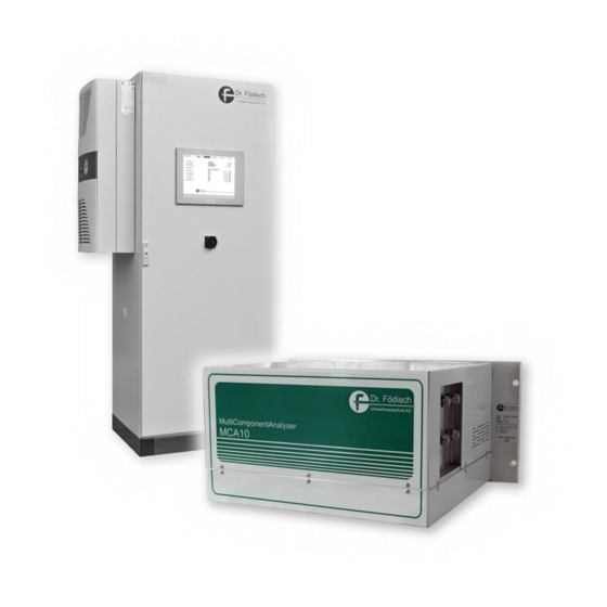
The multi component analyser MCA 10 HWIR serves the continuous emission measurement of pollutants in flue gas. It is applicable all-purpose for measurement of emissions, raw gases or processes. -
Page 7: Warranty
Federal Republic of Germany apply. Declaration of conformity The multi component analyser MCA 10 HWIR has a CE label. Therewith we declare that the device in its conception and design as well as in the execution put into circulation by us corresponds to the fundamental safety and health requirements. -
Page 8: Safety
Notes with signal word “CAUTION” indicate possible hazards which cause material damage in case of non-observing the safety precautions. NOTICE Notes with this indication describe helpful information and tips for operation with the product and serve the avoidance of failure. Operation Manual MCA 10 HWIR Version 3.3... -
Page 9: Specific Safety Instructions
Objects which have been contacted with irritating or corrosive gases or substances must be cleaned accurately. WARNING Hot surface! Several device parts can develop high temperatures. Burn of skin can be caused! For protection against possible injury protective gloves must be worn. Version 3.3 Operation Manual MCA 10 HWIR... -
Page 10: Personal Protective Equipment
For protection against possible eye irritation by corrosive gases or substances eye protection must be worn. WEAR HEARING PROTECTION For protection against possible hearing impairment by high noise level hearing protection must be worn. Operation Manual MCA 10 HWIR Version 3.3... -
Page 11: Requirements For Personnel
Any work at the device must solely be executed by qualified specialised personnel in observation of the corresponding regulations (central association of electrical engineering and industry). Version 3.3 Operation Manual MCA 10 HWIR... -
Page 12: Electrical Power Supply
- If work at the opened device is necessary (adjustment, maintenance etc.), this work must only be executed by appropriate qualified personnel which is familiar with the hazard points and which has knowledge of avoiding hazards by proper safety precaution. Operation Manual MCA 10 HWIR Version 3.3... - Page 13 has visible external damage does not work correctly anymore has been stored under impermissible or inappropriate conditions for any length of time has been encountered impermissible strain during transport Version 3.3 Operation Manual MCA 10 HWIR...
-
Page 14: Gas Supply
In case of standstill for any length of time the bleeder valves of the compressed-gas cylinders respectively of gas supply must be closed, the pressure inside the gas pipes to the device must be released and all valves must be closed. Operation Manual MCA 10 HWIR Version 3.3... -
Page 15: Components
Wear a special ESD wrist band or use a grounded, antistatic working surface. Configuration settings Changes of configuration can endanger the safety and function of the device. Configuration settings must solely be executed by an authorised service technician or by factory personnel of the manufacturer. Version 3.3 Operation Manual MCA 10 HWIR... -
Page 16: Basics
Intensity of emitted light Intensity of received light Extinctions coefficient Concentration of the measured component Transmitted wave length For calculation of gas concentrations in the MCA 10 HWIR three different measuring methods are applied: Bi-frequency measuring method Gas filter correlation ... -
Page 17: Bi-Frequency Measuring Method
Fig. 2: 1 Measuring filter 4 Measuring cell (cuvette) 2 Receiver 5 Light source 3 Reference filter Wave number [cm Bi-frequency measuring method – spectrum Fig. 3: band 3 Measuring filter 2 Reference filter Version 3.3 Operation Manual MCA 10 HWIR... -
Page 18: Gas Filter Correlation
1 Gas filter 4 Free aperture 2 Interference filter 5 Measuring cell (cuvette) 3 Receiver 6 Light source Wave number [cm Gas filter correlation – spectrum Fig. 5: HCl band 2 Interference filter Operation Manual MCA 10 HWIR Version 3.3... -
Page 19: Oxygen Measurement
Due to the proven proportionality of the signal to the concentration a steady exactness in all oxygen concentration ranges is ensured. Oxygen measurement – functional principle Fig. 6: 1 Exhaust 4 Reference medium 2 Pump cell 5 Heater 3 Measuring cell Version 3.3 Operation Manual MCA 10 HWIR... -
Page 20: Compensation Of Measuring Components
compensation required not suitability tested according to DIN EN 15267‑3; certified in compliance with MCERTS Performance Standards Tab. 1: Compensation table Operation Manual MCA 10 HWIR Version 3.3... -
Page 21: Functional Description
Glass industry Chemical industry By the functional principle of the multi component analyser MCA 10 HWIR up to twelve infrared gas components can be detected simultaneously. Optionally, an oxygen measurement is possible by means of an oxygen sensor. The optical bench for the measurement of the infrared components consists primarily of an infrared light source with chopper wheel, a measuring cell, a motor-driven filter wheel and a detector. - Page 22 Thereby the arrangement of the filter wheel is depending on the type of the measured gas ingredients. The multi component analyser MCA 10 HWIR evaluates internally all specification-depending required concentrations with all necessary compensations and standardisations. The mainboard is responsible for all tasks of photometer control, sensor evaluation, concentration calculation and interface communication.
-
Page 23: Design
Device components at the bottom side: Power supply unit Mainboard Fig. 7: Design of multi component analyser MCA 10 HWIR (top view) 1 Measuring cell 5 Pressure sensor of cuvette 2 Emitter unit 6 Oxygen sensor 3 Gas distribution block... -
Page 24: Emitter Unit
5 Design Emitter unit Fig. 8: Emitter unit 1 Infrared emitter 3 Connection for emitter and chopper wheel 2 Focussing mirror 4 Chopper wheel Operation Manual MCA 10 HWIR Version 3.3... -
Page 25: Cuvette
5 Design Cuvette Fig. 9: Cuvette 1 Spherical mirror 4 Mirror S3 2 Couple-in area 5 Couple-out area 3 Mirror S2 Version 3.3 Operation Manual MCA 10 HWIR... -
Page 26: Detector Unit
If the internal temperature resistance displays more than 65 °C, the cuvette heater and the detector heater are set at a target value of 20 °C to avoid detector damages. A failure message is displayed. Operation Manual MCA 10 HWIR Version 3.3... -
Page 27: Gas Distribution Block
Oxygen sensor (optional) The oxygen measurement takes place at exhaust side in the outlet block of the measuring cuvette. The oxygen sensor (6, Fig. 7) is attached above the measuring cuvette. Version 3.3 Operation Manual MCA 10 HWIR... -
Page 28: Mainboard
8 PT100 3 (detector, top) 20 Heater of detector 9 PT100 4 (power supply unit) 21 Filter wheel 10 PT100 5 (injector) 22 Chopper wheel 11 PT100 6 (free) 23 RS232 interface (PLC) 12 Oxygen sensor Operation Manual MCA 10 HWIR Version 3.3... -
Page 29: Power Supply Unit
RS232: communication to cabinet control (PLC), provision of measuring data via Modbus protocol RJ-45: Service interface of factory NOTICE The precise protocol description of Modbus communication can be reviewed in the document “Description for digital interface - Modbus” (see appendix). Version 3.3 Operation Manual MCA 10 HWIR... -
Page 30: Connection Assignment
(suction-side measuring gas input) 2 exhaust: Exhaust connection (screwing-in 4 in 3: Optional measuring gas distribution injector) (suction-side measuring gas input) (All connections with G ¼” for 6/8-type hose resp. tube) Operation Manual MCA 10 HWIR Version 3.3... -
Page 31: System Design (Application Example)
5 Design 5.11 System design (application example) In conjunction with the MCA 10 HWIR the measuring device arises from the following main components: Infrared photometer (MCA 10 HWIR) Analyser cabinet, incl. control panel in the cabinet door ... -
Page 32: Gas Circuit Diagram
5 Design 5.11.1 Gas circuit diagram Forced Propane Fig. 17: Gas circuit diagram (application example) Operation Manual MCA 10 HWIR Version 3.3... - Page 33 The measuring gas conveyance is carried out by the air-jet pump integrated in the MCA 10 HWIR. Forced air of 1 to 4 bar is supplied to this pump. Up to three heated measuring gas pipes can be connected suction-side at the gas distribution block of the analyser module.
-
Page 34: Design Of Cpu Components
PC and analyser. This synchronises itself automatically with the analyser cabinet control. At modification of parameters the complete parameter set is read from the MCA 10 HWIR. Thereby the synchronisation is ensured, so that all current data are transferred at later writing. -
Page 35: Signal Plan
The following figure shows and describes the communication paths and tasks of the system components. The signal connection to the control system is solely done via the control unit of the analyser cabinet (PLC). Fig. 19: Signal plan (application example) Version 3.3 Operation Manual MCA 10 HWIR... -
Page 36: Transport And Scope Of Supply
Depending on purchase configuration deviations in technical design are possible, e.g. by analyser cabinet or optional additional devices. 1. Check the scope of supply for completeness and intactness. 2. Remove the packaging material. 3. Keep the packaging material for possible re-use. Operation Manual MCA 10 HWIR Version 3.3... -
Page 37: Placement And Mounting
Placement and mounting Placement CAUTION The device must not be operated in potentially explosive atmosphere. For correct operation of the multi component analyser MCA 10 HWIR the following ambient conditions apply: Ambient temperature: 25...35 °C (temperature stability max. 2 K/h) ... -
Page 38: Commissioning
The correct operation of ventilation in the analyser cabinet must be assured. NOTICE If the MCA 10 HWIR shall be commissioned again after storage, before commissioning it must stand unused at installation location at least one day under permissible ambient conditions. -
Page 39: Test Gas Provision
8 Commissioning Test gas provision WARNING Hot surface! The MCA 10 HWIR is standard heated to a temperature of 185 °C. Burn hazard! Personal protective equipment according to the current legal accident prevention regulations must be worn. CAUTION Before test gas provision a stable zero point setting must have been carried out (control of drift correction values not more than 0.2 %/h). -
Page 40: Software Installation
For installation of the PC software “MCA10_HID” of Dr. Födisch Umweltmesstechnik AG the following preconditions must be fulfilled: Communications cable between PC and MCA 10 HWIR connected (USB, connection C4) MCA 10 HWIR and PC switched on ... -
Page 41: Operating
Basic requirement for safe operating is exact knowledge of the functioning of the MCA 10 HWIR and the complete system as well as knowledge of measuring method, windows-based applications and system-dependent details. For operation with the software the instructions and calibration directions must be obeyed exactly. -
Page 42: Display And Operating Elements
Maintenance is required. The list of the current messages has to be reviewed. maintenance The device is in maintenance mode. Modifications are active. failure A failure currently exists. The list of the current messages has to be reviewed. Operation Manual MCA 10 HWIR Version 3.3... -
Page 43: Display And Operating Elements Within Menus
In case of an active maintenance or an upcoming failure of the communication status of the MCA 10 HWIR an additional message (8, Fig. 20) is displayed at the left side of the lower status bar. In normal operational state the display does not contain any messages. - Page 44 5 Button “Del” (delete input value) 9 Title/value name Function button By clicking a function button a function is carried out directly. The respective function is specified as clear text on the button. Operation Manual MCA 10 HWIR Version 3.3...
-
Page 45: Display "Data Transfer
CAUTION During data transfer the USB connection must not be interrupted. The data transfer between MCA 10 HWIR and PC serves the synchronisation of data and is started automatically. An automatic data transfer is carried out at the following actions: Starting of the user software “MCA10_HID”... -
Page 46: Menu Structure
9 Operating Menu structure concentration measurement development system control diagnostics IR-components (example) (example) (other components) -sensor detector heater cuvette injector -sensor (external heater circuits) pressure cuvette injector flow general Fig. 22: Menu structure (1/3) Operation Manual MCA 10 HWIR Version 3.3... - Page 47 9 Operating current messages messages history auto calibration calibration IR zero point IR span point manually (example) -sensor (example) flow (other components) drift correction Fig. 23: Menu structure (2/3) Version 3.3 Operation Manual MCA 10 HWIR...
- Page 48 The selection of the possible interference heater detector component is available for additive as well as multiplicative interference. cuvette injector -sensor (external heater circuits) pressure cuvette injector flow system general password back purging Fig. 24: Menu structure (3/3) Operation Manual MCA 10 HWIR Version 3.3...
-
Page 49: Password Levels
9 Operating Password levels For operating the user software of the MCA 10 HWIR four password levels are existing. As standard, these are configured as follows: Password level Access facilities View of all IR measuring values, diagnostic values and messages ... -
Page 50: Main Menu
NOTICE The designation of the software version is subdivided into three parts and marked by lines. The designation of the separate software versions is due to the following: PC | MCA | SPS Operation Manual MCA 10 HWIR Version 3.3... -
Page 51: Change Language
4. Acknowledge the input with “Enter”. › The password is adopted and the access to the respective level is enabled. NOTICE After 60 min without operating activity the menu is automatically reset to password level 0. Version 3.3 Operation Manual MCA 10 HWIR... -
Page 52: Measurement
By clicking the arrow button the next screen page is selected. By clicking the button “development” (2, Fig. 26) the display of concentration development for the respective component is opened (see Fig. 27, page 53). Operation Manual MCA 10 HWIR Version 3.3... - Page 53 NOTICE Through going forward/back within the time axis the automatic actualisation of the diagram is deactivated. To reactivate the automatic actualisation, a click into the diagram must be done. Version 3.3 Operation Manual MCA 10 HWIR...
-
Page 54: System Control
By clicking the respective selection field (1, Fig. 28) the maintenance mode is switched on/off. System By clicking the respective selection field (2, Fig. 28) the measuring/zero/test gas can be provided. The selection is also possible in case of an automatic test gas provision. Operation Manual MCA 10 HWIR Version 3.3... -
Page 55: Diagnostics
Heater (subordination of the second selection list: detector, cuvette, injector, O -sensor and external heater circuits (optional)) Pressure (subordination of the second selection list: cuvette, injector) Flow (analyser flow) General Version 3.3 Operation Manual MCA 10 HWIR... -
Page 56: Messages
Specific messages, e.g. an active zero point routine or a failure of the communication status, are additionally displayed in the lower status bar (2). Under normal operation conditions there are no entries in the overview. Operation Manual MCA 10 HWIR Version 3.3... - Page 57 Date and time are only registered if the communication to the PLC with required timestamp is ensured. The actualisation of the history must be carried out manually by clicking the button “update” (1). Version 3.3 Operation Manual MCA 10 HWIR...
-
Page 58: Auto Calibration
IR components is set. After another run-in period the system is switched back into operation mode. Depending on configuration an additional calibration of the span point of the oxygen sensor is set to 20.95 vol. %. Operation Manual MCA 10 HWIR Version 3.3... -
Page 59: Calibration
IR zero point IR span point manually (subordination of the second selection list: all measurable components) IR span point automatically (optional) -sensor Flow (analyser flow) Drift correction Version 3.3 Operation Manual MCA 10 HWIR... - Page 60 Span point setting: The analyser must be purged with zero gas and must be stabilised. At executing the respective function the zero point respectively the span point of the O -sensor is calibrated. Operation Manual MCA 10 HWIR Version 3.3...
- Page 61 Drift correction At executing the function the drift value saved after a zero point setting is reset to zero. Version 3.3 Operation Manual MCA 10 HWIR...
-
Page 62: Configuration
1 Display of menu content 3 Third selection list * (example - depending on selection) 4 Second selection list * 2 Fourth selection list * 5 First selection list * depending on pre-selection Operation Manual MCA 10 HWIR Version 3.3... - Page 63 (optional) can be reviewed and modified via the menu. Pressure Depending on the setting in the second selection list, parameters of the pressure of cuvette and injector can be reviewed and modified via the menu. Version 3.3 Operation Manual MCA 10 HWIR...
-
Page 64: Service Mode
Via the menu the parameters for back purging can be reviewed and modified. 9.12 Service mode NOTICE The service mode enables unlimited access which is exclusively reserved for authorised service personnel of Dr. Födisch Umweltmesstechnik AG. The screen is accessible only for password level 4. Operation Manual MCA 10 HWIR Version 3.3... -
Page 65: Maintenance/Upkeep
Exchange 6 months Sinter metal filter of cuvette Exchange 12 months Gaskets at cuvette inlet Exchange 12 months block Screwing-in with nozzle at Exchange 24 months gas distribution block Tab. 4: Maintenance/upkeep work Version 3.3 Operation Manual MCA 10 HWIR... -
Page 66: Exchange Injector Screwing-In
8. Dismount the sinter metal filter and the gaskets. 9. Mount the new sinter metal filter and the new gaskets. 10. Replace the gaskets of the cuvette inlet block with new gaskets. 11. Fix the circlip. Operation Manual MCA 10 HWIR Version 3.3... -
Page 67: Exchange Screwing-In With Nozzle At Gas Distribution Block
9. Close the cuvette isolation box and screw it with the four hexagon socket-head screws. 10. Put the upper device cover onto the device and screw it. 11. Check the device for leak tightness. 12. Connect the device to the power supply. Version 3.3 Operation Manual MCA 10 HWIR... -
Page 68: Error Search And Failure Clearance
Service qualification of the specialised personnel CAUTION Actions for failure clearance which exceed the service qualification of the trained qualified personnel of level 3 must solely be executed by service personnel of Dr. Födisch Umweltmesstechnik AG. Operation Manual MCA 10 HWIR Version 3.3... -
Page 69: Displaying Of Current Messages And Clearing Of Failures
9.8 “Messages”, page 56). In case of a system application, current failure messages according to communication status of MCA 10 HWIR and PLC are additionally displayed in the lower status bar on the screen. 1. Select menu “messages” on operating surface. -
Page 70: Messages "Failure
Exchange the cuvette inlet filter. faulty flow measurement Calibrate the flow measurement via the menu of the operating surface (see section 9.10 “Calibration”, page 59). miscellaneous Contact Dr. Födisch Umweltmesstechnik AG. Operation Manual MCA 10 HWIR Version 3.3... - Page 71 Switch the DIP switch at the control unit in the (“PROG.”) system cabinet to “RUN”. MCA - PLC unconnected or defect Check the connection cable between MCA 10 HWIR connection cable between and PLC. MCA 10 HWIR and PLC Exchange it, if necessary.
- Page 72 Contact Dr. Födisch Umweltmesstechnik AG. message heating option intern temporary occurring failure Wait until the message has disappeared. hardware failure message (without relevance) permanently occurring failure Contact Dr. Födisch Umweltmesstechnik AG. message Operation Manual MCA 10 HWIR Version 3.3...
- Page 73 62). Correct these, if necessary. controller error Carry out a reset of the analyser (see section 12.1 “Shutdown”, page 89 and section 8.1 “Commissioning of MCA 10 HWIR”, page 38). Wait until the heat-up phase is finished. defect oxygen sensor Exchange the oxygen sensor.
- Page 74 (see section 9.11 “Configuration”, faulty page 62). Correct these, if necessary. defect detector heater Exchange the detector heater. defect temperature sensor Exchange the temperature sensor. miscellaneous Contact Dr. Födisch Umweltmesstechnik AG. Operation Manual MCA 10 HWIR Version 3.3...
- Page 75 Check the parameter settings in the menu of the operating surface (see section 9.11 “Configuration”, faulty page 62). Correct these, if necessary. defect temperature sensor Exchange the temperature sensor. miscellaneous Contact Dr. Födisch Umweltmesstechnik AG. Version 3.3 Operation Manual MCA 10 HWIR...
- Page 76 (see section 9.11 “Configuration”, faulty page 62). Correct these, if necessary. defect injector heater Exchange the injector heater. defect temperature sensor Exchange the temperature sensor. miscellaneous Contact Dr. Födisch Umweltmesstechnik AG. Operation Manual MCA 10 HWIR Version 3.3...
- Page 77 62). Correct these, if necessary. zero gas rate too high Regulate the zero gas rate to the system-specific nominal value (reviewable in the system-specific supplementary sheet for MCA 10 HWIR). defect injector heater Exchange the injector heater. defect temperature sensor Exchange the temperature sensor.
- Page 78 Check the electric connections of heater and temperature sensor. defect probe heater Exchange the probe heater. defect temperature sensor Exchange the temperature sensor. miscellaneous Contact Dr. Födisch Umweltmesstechnik AG. Error search and failure clearance – Messages “failure” Tab. 6: Operation Manual MCA 10 HWIR Version 3.3...
-
Page 79: Messages "Maintenance
FID is active Select the menu “FID control” on the operating maintenance at FID surface of the MCA 10 HWIR. Check the message display of the FID. If applicable, eliminate the respective cause of error/failure. For that purpose, read the technical documentation of the supplier (see appendix). - Page 80 Set the system via the menu of the operating surface to “measuring gas” (see section 9.6 “System control”, page 54). Error search and failure clearance – Messages “maintenance” Tab. 7: Operation Manual MCA 10 HWIR Version 3.3...
-
Page 81: Messages "Maint. Req
Contact Dr. Födisch Umweltmesstechnik AG. Select the menu “FID control” on the operating maintenance requirement at surface of the MCA 10 HWIR. Check the message display of the FID. If applicable, eliminate the respective cause of error/failure. For that purpose, read the technical documentation of the supplier (see appendix). - Page 82 Check the parameter settings in the menu of the operating surface (see section 9.11 “Configuration”, faulty page 62). Correct these, if necessary. miscellaneous Contact Dr. Födisch Umweltmesstechnik AG. Operation Manual MCA 10 HWIR Version 3.3...
- Page 83 (see section 9.11 “Configuration”, faulty page 62). Correct these, if necessary. defect cuvette heater Exchange the cuvette heater. defect temperature sensor Exchange the temperature sensor. miscellaneous Contact Dr. Födisch Umweltmesstechnik AG. Version 3.3 Operation Manual MCA 10 HWIR...
- Page 84 Check the parameter settings in the menu of the operating surface (see section 9.11 “Configuration”, faulty page 62). Correct these, if necessary. defect temperature sensor Exchange the temperature sensor. miscellaneous Contact Dr. Födisch Umweltmesstechnik AG. Operation Manual MCA 10 HWIR Version 3.3...
- Page 85 Check the electric connections of heater and temperature sensor. defect heater of the Exchange the measuring gas pipe. measuring gas pipe defect temperature sensor Exchange the measuring gas pipe. miscellaneous Contact Dr. Födisch Umweltmesstechnik AG. Version 3.3 Operation Manual MCA 10 HWIR...
- Page 86 62). Correct these, if necessary. zero gas rate too high Regulate the zero gas rate to the system-specific nominal value (reviewable in the system-specific supplementary sheet for MCA 10 HWIR). defect injector heater Exchange the injector heater. defect temperature sensor Exchange the temperature sensor.
- Page 87 62). Correct these, if necessary. defect electric connections Check the electric connections of heater and temperature sensor. defect probe heater Exchange the probe heater. defect temperature sensor Exchange the temperature sensor. miscellaneous Contact Dr. Födisch Umweltmesstechnik AG. Version 3.3 Operation Manual MCA 10 HWIR...
-
Page 88: Info Message
Check the connection cable between visualisation connection cable between PC and MCA 10 HWIR. Exchange it, if necessary. visualisation PC and MCA 10 HWIR miscellaneous Contact Dr. Födisch Umweltmesstechnik AG. -
Page 89: Shutdown And Disposal
1. Purge the device with zero gas for min. 30 min. 2. Disconnect the measuring gas pipe from gas sampling. Therefor shut the valves at the gas bottles. 3. Disconnect the power plug from power supply. Version 3.3 Operation Manual MCA 10 HWIR... -
Page 90: Disassembling
7. Store all pipes safe and care for correct storage of the device. 12.3 Storage For correct storage of the multi component analyser MCA 10 HWIR the following ambient conditions apply: Ambient temperature: 0 ... 50 °C ... -
Page 91: Technical Data
13 Technical data Technical data 13.1 Multi component analyser MCA 10 HWIR Multi component analyser MCA 10 HWIR Insulation protection class I according to IEC 1010-1:1993 Insulation co-ordination overvoltage category II according to IEC 1010-1:1993 Protection degree IP40 Pollution pollution degree 2 according to... - Page 92 Operating PC connection via USB Interfaces 2 x RS 232, USB Software versions [PC/MCA10/PLC] 4.00/3.61/3.62 Technical data – Multi component analyser MCA 10 HWIR Tab. 10: Photometer Spectral range 1 ... 16 µm Supply voltage of emitter unit 10 V Gas line, heated continuous to 200 °C, standard 185 °C,...
-
Page 93: Measuring Ranges Of Mca 10 Hwir
13 Technical data 13.2 Measuring ranges of MCA 10 HWIR For measurement of the various gas concentrations the MCA 10 HWIR is tested regarding the following measuring ranges: Component Certification range Measuring range 2 Measuring range 3 0...75 mg/m³ 0...300 mg/m³... -
Page 94: Spare And Wear Parts
Cuvette ETLD 19 Detector board ETLD 118 Detector box ETLD 18 Elbow screwing ETLA 690 Elbow screwing of pressure sensor ETLD 154 Emitter box ETLD 17 Fan for power supply unit ETLD 467 Operation Manual MCA 10 HWIR Version 3.3... - Page 95 PTFE hose 146 mm ETLD 327 PTFE hose 240 mm ETLD 329 PTFE hose 4/6 ETLD 75 PTFE hose 46 mm ETLD 326 PTFE hose 560 mm ETLD 331 Screw-in connection with gasket ETLD 322 Version 3.3 Operation Manual MCA 10 HWIR...
- Page 96 Stud bolt for gas distribution block ETLD 43 Thermo switch ETLA 264 Touch pen ETLD 632 Window holder ETLD 80 Spare and wear parts – Multi component analyser MCA 10 HWIR Tab. 13: Operation Manual MCA 10 HWIR Version 3.3...
-
Page 97: System Application With Analyser Cabinet
PLC as well as a pressured air distribution are located inside. The multi component analyser MCA 10 HWIR is mounted rear at the mounting plate. In the steel sheet door the control panel with touch surface is generally located. -
Page 98: Transport Of Analyser Cabinet
Consider the barycentre of analyser cabinet when lifting. 1. Check the analyser cabinet as well as the packaging material for transport damage. 2. Document possibly existing damage. 3. Remove the packaging material. 4. Keep the packaging material for possible re-use. Operation Manual MCA 10 HWIR Version 3.3... -
Page 99: Placement And Mounting
2. Remove all means of transport (ropes, chains etc.) and hoisting lugs if necessary. 3. Align the analyser cabinet with the aid of a spirit level. 4. Tighten the analyser cabinet at the wall/ground. Version 3.3 Operation Manual MCA 10 HWIR... -
Page 100: Mounting
Insufficient ventilation can cause damage at the device. Take care that the ventilation slots are not covered. 9. Execute the following work at the MCA 10 HWIR: a) Connect the measuring gas pipe, the exhaust pipe and if necessary additional devices with the connections at the right device side (see Fig. -
Page 101: Commissioning
Any work at the device must solely be executed by qualified personnel. NOTICE If the MCA 10 HWIR shall be commissioned again after storage, before commissioning it must stand unused at installation location at least one day under permissible ambient conditions. -
Page 102: Automatic Zero Point Setting Via "Thermocal
2.0 K, the function “Thermocal” is triggered. Thereby the MCA 10 HWIR is purged with instrument air with a delay of two hours and the zero point is set. The function “Thermocal” happens in maintenance mode. -
Page 103: Test Gas Provision
Test gas provision The test gas provision can be carried out locally via the gas distribution block at the MCA 10 HWIR or by overflow process via gas sample probe. NOTICE Generally, a test gas provision via gas sample probe is recommended. -
Page 104: Local Test Gas Provision At Mca 10 Hwir
15 System application with analyser cabinet 15.6.1 Local test gas provision at MCA 10 HWIR (See section 8.2 “Test gas provision”, page 39) 15.6.2 Test gas provision via gas sample probe (optional) NOTICE For operation with the gas sample probe please read the technical documentation of the supplier (see appendix). - Page 105 1. Close the test gas supply. 2. Remove the pipes of test gas provision from the test gas connection (1, Fig. 37). 3. Switch the system into operation mode by the maintenance switch at the analyser cabinet. Version 3.3 Operation Manual MCA 10 HWIR...
-
Page 106: Maintenance/Upkeep
The contents are at responsibility of the respective manufacturers. 15.8 Error search and failure clearance NOTICE Error search and failure clearance for the system are carried out according to the MCA 10 HWIR (see chapter 11, page 68). Operation Manual MCA 10 HWIR Version 3.3... -
Page 107: Shutdown And Disposal
3. Switch off the compressed-air supply of the analyser cabinet. 4. Switch off the power supply by the master switch at the analyser cabinet. › The MCA 10 HWIR, the air conditioner of the analyser cabinet and if necessary connected optional additional devices are switched off automatically. Version 3.3... -
Page 108: Disassembling
2. Disconnect the signal connection from the control system. 3. Execute the following work at the MCA 10 HWIR: a) Disconnect the power cord of the MCA 10 HWIR from the terminal strip in the analyser cabinet. b) Disconnect the communication cables of PLC and PC from the device. -
Page 109: Technical Data
2100 mm x 800 mm x 600 mm (H x W x D) Material Steel sheet Weight Approx. 200 ... 300 kg (depending on fitments) Colour RAL 7035 (light grey) Operating unit Control panel with touch surface Technical data – Analyser cabinet Tab. 16: Version 3.3 Operation Manual MCA 10 HWIR... -
Page 110: Spare And Wear Parts
Locking screw M63x1.5 ETLA 187 Multiple-port plate ETLD 316 Null modem cable ETLD 349 Pass element ETLD 353 ETLD 324 PLC programming cable for PC ETLA 598 Plug connector screwing with hexagon socket ETLD 315 Operation Manual MCA 10 HWIR Version 3.3... - Page 111 ETLD 323 Throttle non-return valve ETLD 320 Thyristor power switch ETLA 634 Touch panel ETLD 498 / ETLD 52 USB cable ETLD 350 Spare and wear parts – System / Analyser cabinet Tab. 17: Version 3.3 Operation Manual MCA 10 HWIR...
-
Page 112: Index
Device information ....... 50 CE label ..........7 Diagnostics .......... 55 Certification range ....... 93 Disassembling MCA 10 HWIR ..... 90 Chopper wheel ........24 Disassembling of analyser cabinet ..108 Commissioning MCA 10 HWIR ... 38 Display and operating elements ..42 Software installation ...... - Page 113 Main menu .......... 50 Electrical power supply ....... 12 Mainboard ........... 28 Electrical safety ........13 Maintenance MCA 10 HWIR ....65 Electronic elements ......15 Maintenance message .... 42, 56, 79 Emitter unit ........23, 24 Maintenance of analyser cabinet..106 Error search ........
- Page 114 Data transfer ........45 Diagnostics ........55 Display and operating elements ..42 Safety instructions ......... 8 Main menu ........50 Scope of supply MCA 10 HWIR ..36 Measurement ........ 52 Selection field ........43 Menu structure....... 46 Selection list ........43 Messages ........
- Page 115 16 Index Technical data MCA 10 HWIR ..91, 92 Value input .......... 44 Certification range and measuring ranges ........... 93 Technical data of analyser cabinet ... 109 Technical data of system ....109 Warranty ..........7 Wear parts MCA 10 HWIR ....94 Temperature sensor ......
Need help?
Do you have a question about the MCA 10 HWIR and is the answer not in the manual?
Questions and answers