
Related Manuals for Dr.Fodisch PFM 92 C


Summary of Contents for Dr.Fodisch PFM 92 C
- Page 1 Particle Flow Meter PFM 92 C Operation manual Dr. Födisch Umweltmesstechnik AG Telephone: +49-34205-755-0 Zwenkauer Strasse 159 Fax: +49-34205-755-40 D - 04420 Markranstädt e-mail: info@foedisch.de Internet: www.foedisch.de...
- Page 2 Dr. Födisch Umweltmesstechnik AG. Any violation obliges to compensate the loss. All rights are reserved for the case of a registration of a patent, utility patent or design patent. Page 2 of 30 Operation manual PFM 92 C Version 3.0...
-
Page 3: Table Of Contents
Set up Operation and handling Measuring signal......................20 Adjust amplification....................20 Selection of operation mode..................21 Adjust limit values ....................23 Shut down Dis-assembly ......................24 Disposal ........................25 Maintenance Maintenance ......................26 8.1.1 Maintenance works....................26 Cleaning........................26 Version 3.0 Operation manual PFM 92 C Page 3 of 30... - Page 4 Failure elimination Failure ........................27 Technical data Spare parts & consumables Index Figures Fig. 3.1: Side view PFM 92 C ................... 11 Fig. 3.2: Measuring principle..................... 12 Fig. 4.1: Entry and exit section..................13 Fig. 4.2: Weld-in sleeve ....................14 Fig.
-
Page 5: General Remarks
Advices for handling the manual In the manual it is described how you can mount, set up, control and maintain the measuring equipment. Please pay especially attention to texts of warning and advices. Version 3.0 Operation manual PFM 92 C Page 5 of 30... -
Page 6: Warning Advices
Correct and safe operation of this analyser is additionally dependent on proper transport, storage, installation and assembly, as well as careful operation and maintenance. Page 6 of 30 Operation manual PFM 92 C Version 3.0... -
Page 7: Qualified Personnel
Changes in design or construction of the filter controller are not allowed. Any intervention lead to a termination of the warranty. Version 3.0 Operation manual PFM 92 C Page 7 of 30... -
Page 8: Supply And Delivery
The Particle Flow Meter PFM 92 C complies with the requirements of the EU guidelines listed below. EG-low voltage directive The Particle Flow Meter PFM 92 C complies with the requirements of the EU low voltage directive 2006/95/EG dated 12. Dezember 2006. EMC-Guideline The Particle Flow Meter PFM 92 C complies with the requirements of the EU guideline 89/336/EEC “Electromagnetic Compatibility”... - Page 9 In line with the above-mentioned EU guidelines, the EU declarations of conformity are available at the following address for inspection by appropriate authorities: Dr. Födisch Umweltmesstechnik AG Zwenkauer Straße 159 D-04420 Markranstädt Tel.: +49-34205-755-0 Fax.: +49-34205-755-40 e-Mail: sales@foedisch.de Version 3.0 Operation manual PFM 92 C Page 9 of 30...
-
Page 10: Safety Advices
Before the PFM 92 C is allowed to be used, the complete manual must have been read and understood. The PFM 92 C as a whole as well as the single components are only allowed to be operated in the original state. If elements are changed the manufacturer’s original parts shall be used. -
Page 11: Structure And Function
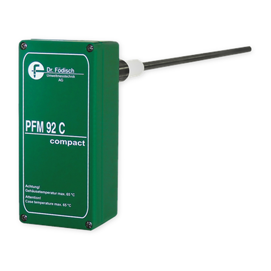
1 weld-in sleeve 3.1.1 Probe The probe PFM 92 C consists of a probe rod and a probe head. The probe rod is assembled in a sleeve and an insulator which insulates it electrically from the case. 300 mm 146 mm... -
Page 12: Function
3 Structure and function Function The filter controller PFM 92 C is a highly sensitive system for continuous, triboelectric in- situ filter monitoring. The qualitative monitoring of the exhaust gas is done hereby. The measuring gas is measured triboelectrically in the exhaust gas flow by means of the probe rod of the PFM 92 C (see 3.2.1 Measuring principle Page 12). -
Page 13: Installation
– section. WARNING Risk of measuring failures. The probe profile should be protected against rain falling down! Version 3.0 Operation manual PFM 92 C Page 13 of 30... -
Page 14: Installation Of The Weld-In Sleeve
Dr. Födisch Umweltmesstechnik 4 Installation Installation of the weld-in sleeve The weld-in sleeve of the PFM 92 C is installed according to Fig. 4.2: Weld-in sleeve The installation position of the probe is horizontal or vertical from top. 3 mm... -
Page 15: Electric Connection
The measuring device PFM 92 C must not be opened in potentially explosive dust atmosphere! The electric connections of the PFM 92 C are inside the probe head. The terminals are arranged in a terminal strip which can be seen after removal of the cover. To get there 4 screws have to be unscrewed and the cover has to be removed. -
Page 16: Operational Voltage (24 Vdc)
0-1Volt = 0-100% ATTENTION: Connect power supply only on this terminals! Fig. 4.5: Electric connection 24 VDC WARNING The operational voltage 24 VDC is connected to the terminals 1 and 2! Page 16 of 30 Operation manual PFM 92 C Version 3.0... -
Page 17: Operational Voltage (110/230 Vac)
ATTENTION: Connect power supply only on this terminals! Fig. 4.6: Electric connection 110/230 VAC WARNING The operational voltage 110/230 VAC is connected to the terminals 1, 2 and 3! Version 3.0 Operation manual PFM 92 C Page 17 of 30... -
Page 18: Status Signals
4.4.4 Analogue output The analogue output of the PFM 92 C is made as 4 ... 20 mA output. An external analogue separator has to be used for the galvanic isolation of the output signal. The following signal can be provided by the PFM 92 C: Analogue output ->... -
Page 19: Set Up
3. Adjust measuring range / amplification , if necessary (see 6.2 Adjust amplification Page 20) 4. Adjust operation mode, if necessary (see 6.3 Selection of operation mode Page 21) 5. Adjust limit values (see 6.4 Adjust limit values Page 23) Version 3.0 Operation manual PFM 92 C Page 19 of 30... -
Page 20: Operation And Handling
After all electric connections have been made, the device is ready for operation within ca. 10 to 15 min. All control elements of the PFM 92 C are on the signal board – a selector switch for the amplification [S2], a switch for the selection of the operation mode integration [S1] and a tip button [S3] for adjustment of the limit values as well as diverse LED –... -
Page 21: Selection Of Operation Mode
The zero point is adjusted at factory. Selection of operation mode The PFM 92 C has 2 operation modes. In operation mode Integral On (LED [L1] Integration flashes yellow) the measuring signal is averaged with a time constant of ca. 30 s. -
Page 22: Fig 6.1: Filter Diagram With Defective Filter Bags
Dr. Födisch Umweltmesstechnik 6 Operation and handling Fig 6.1: Filter diagram with defective filter bags Fig. 6.2: Filter diagram with sound filter bags Page 22 of 30 Operation manual PFM 92 C Version 3.0... -
Page 23: Adjust Limit Values
LED goes out and the respective limit value contact is opened. WARNING Risk by non-observance of the safety advices! The measuring device PFM 92 C must not be opened in potentially explosive dust atmosphere! Version 3.0 Operation manual PFM 92 C... -
Page 24: Shut Down
Then the screw is unscrewed and the probe can be taken out. 2. release quick clamp probe head 3. remove probe probe rod (1. interrupt power supply) flue gas stack cable entry Fig. 7.1: Disassembly Page 24 of 30 Operation manual PFM 92 C Version 3.0... -
Page 25: Disposal
Umweltmesstechnik 7 Shut down Disposal HINT The disposal of the PFM 92 C has to be done according to locally valid environmental protection regulations. In case of disposal the PFM 02 has to be treated as hazardous waste. Version 3.0... -
Page 26: Maintenance
Table 8.1: Maintenance works Cleaning The dust measuring device PFM 92 C has to be cleaned at least every 6 months. The frequency of cleaning works to be done depends on the chosen measuring position respectively the measuring media (especially the dust content) and on the environmental and climatic conditions. -
Page 27: Failure Elimination
If failures or errors occur, which cannot be eliminated by the measures described hereinafter, contact the Dr. Födisch Umweltmesstechnik AG (see cover inside). The PFM 92 C supplies status signals for monitoring, signalling failure states and failure search. They are provided at the status contacts as potential-free contact. Failure... -
Page 28: Technical Data
Limit value 1 (in case of limit value violation open) contact normally closed Limit value 2 (in case of limit value violation open) Table 10.1: Technical data Page 28 of 30 Operation manual PFM 92 C Version 3.0... -
Page 29: Spare Parts & Consumables
Dr. Födisch Umweltmesstechnik 11 Spare parts & consumables Spare parts & consumables In order to purchase spare parts and consumables please contact Dr. Födisch Umweltmesstechnik AG (see cover inside) Version 3.0 Operation manual PFM 92 C Page 29 of 30... -
Page 30: 12 Index
WARNING 6, 7, 10, 13, 24, 26 Warranty 7, 26 HINT 6, 8, 25, 27 Weld-in sleeve 14 Installation 13 Zero point 21 Installation position 14 Integration 21 Limit 23 limit values 18 Page 30 of 30 Operation manual PFM 92 C Version 3.0...
Need help?
Do you have a question about the PFM 92 C and is the answer not in the manual?
Questions and answers