Table of Contents
Advertisement
Quick Links
UM3109
User manual
A guide for using the VL53L8CX, low-power, high-performance Time-of-Flight
multizone ranging sensor
Introduction
The purpose of this user manual is to explain how to handle the VL53L8X Time-of-Flight (ToF) sensor, using the ultra lite driver
(ULD) API. It describes the main functions to program the device, the calibrations, and the output results.
Based on ST's FlightSense technology, the VL53L8CX incorporates an efficient metasurface lens (DOE) placed on the laser
emitter enabling the projection of a 45° x 45° square FoV onto the scene.
Its multizone capability provides a matrix of 8x8 zones (64 zones) and can work at fast speeds (60 Hz) up to 400 cm.
Thanks to the autonomous mode with programmable distance threshold, the VL53L8CX is perfect for any application requiring
low-power user detection. ST's patented algorithms and innovative module construction allow the VL53L8CX to detect, in each
zone, multiple objects within the FoV with depth understanding. ST histogram algorithms ensure cover glass crosstalk immunity
beyond 60 cm.
Like all Time-of-Flight (ToF) sensors based on ST's FlightSense technology, the VL53L8CX records, in each zone, an absolute
distance regardless of the target color and reflectance.
Housed in a miniature reflowable package that integrates a SPAD array, the VL53L8CX achieves the best ranging performance
in various ambient lighting conditions, and for a wide range of cover glass materials.
All of ST's ToF sensors integrate a VCSEL that emits a fully invisible 940 nm IR light, which is totally safe for the eyes (Class 1
certification).
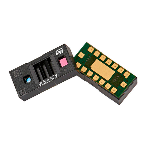
Figure 1.
VL53L8CX sensor module
References
VL53L8CX datasheet (DS14161).
UM3109 - Rev 1 - January 2023
www.st.com
For further information contact your local STMicroelectronics sales office.
Advertisement
Table of Contents

Related Manuals for ST VL53L8CX


Summary of Contents for ST VL53L8CX
- Page 1 All of ST's ToF sensors integrate a VCSEL that emits a fully invisible 940 nm IR light, which is totally safe for the eyes (Class 1 certification).
-
Page 2: Acronyms And Abbreviations
UM3109 Acronyms and abbreviations Acronyms and abbreviations Acronym/abbreviation Definition diffractive optical element field of view inter-integrated circuit (serial bus) Kilo-count per second per spad (unit used to quantify the Kcps/SPAD number of photons into the SPAD array) random access memory serial clock line serial data SPAD... -
Page 3: Functional Description
Functional description System overview The VL53L8CX system is composed of a hardware module and the ultra lite driver software (VL53L8CX ULD) running on a host (see figure below). The hardware module contains the ToF sensor. STMicroelectronics delivers the software driver, which is referred to in this document as "the driver". This document describes the functions of the driver, which are accessible to the host. -
Page 4: Schematics And I2C/Spi Configuration
VL53L8CX datasheet. The VL53L8CX device has a default I2C address of 0x52. However, it is possible to change the default address to avoid conflicts with other devices, or to facilitate adding multiple VL53L8CX modules to the system for a greater system FoV. - Page 5 UM3109 Schematics and I2C/SPI configuration Figure 5. Multiple sensors on SPI To allow a device to have its I2C address changed without affecting others on the I2C bus, it is important to disable the I2C communication of the devices not being changed. The procedure is as follows: Power up the system as normal.
-
Page 6: Package Content And Data Flow
Package content and data flow Driver architecture and content The VL53L8CX ULD package is composed of four folders. The driver is located in the folder / VL53L8CX_ULD_API. The driver is composed of mandatory and optional files. Optional files are plugins used to extend ULD features. -
Page 7: Calibration Flow
Xtalk calibration may be required if the module is protected by a cover glass. The VL53L8CX is immune to Xtalk beyond 60 cm thanks to a histogram algorithm. However, at short distances below 60 cm, Xtalk can be larger than the actual returned signal. -
Page 8: Ranging Flow
The following figure represents the ranging flow used to get measurements. Xtalk calibration and optional function calls must be used before starting the ranging session. The get/set functions cannot be used during a ranging session, and 'on-the-fly' programming is not supported. Figure 8. Ranging flow using VL53L8CX UM3109 - Rev 1 page 8/20... -
Page 9: Available Features
UM3109 Available features Available features The VL53L8CX ULD API includes several functions, which allow the user to tune the sensor, depending on the use case. All the functions available for the driver are described in the following sections. Initialization Initialization must be done before using the VL53L8CX sensor. This operation requires the user to: Power on the sensor (VDDIO, AVDD, CORE_1V8, and LPn pins set to High Call the function vl53l8cx_init(). -
Page 10: Ranging Mode
UM3109 Ranging mode Ranging mode Ranging mode allows the user to choose between ranging in high performance or low power consumption. There are two modes proposed: • Continuous: The device continuously grabs frames with a ranging frequency defined by user. The VCSEL is enabled during all ranging, so maximum ranging distance and ambient immunity are better. -
Page 11: Power Modes
UM3109 Power modes Power modes Power modes can be used to reduce the power consumption when the device is not used. The VL53L8CX can operate in one of the following power modes: • Wake-up: The device is set in HP idle (high power), waiting for instructions. -
Page 12: Target Order
Example of histogram with 2 targets 4.10 Multiple targets per zone The VL53L8CX can measure up to four targets per zone. The user can configure the number of targets returned by the sensor. Note: The minimum distance between two targets to be detected is 600 mm. -
Page 13: Detection Thresholds
4.14 Motion indicator The VL53L8CX sensor has an embedded Firmware feature allowing motion detection in a scene. The motion indicator is computed between sequential frames. This option is available using the plugin ‘vl53l8cx_plugin_motion_indicator’. The motion indicator is initialized using the vl53l8cx_motion_indicator_init() function. If the user wants to change the sensor resolution, he must update the motion indicator resolution using the dedicated function: vl53l8cx_motion_indicator_set_resolution(). -
Page 14: External Synchronization Pin
An external trigger source can be used to synchronize acquisitions. When the external synchronization is enabled, the VL53L8CX waits for an interrupt on the SYNC pin to start the next acquisition. To use this feature, the SYNC pin (B1) needs to be connected as described in the product datasheet. -
Page 15: Ranging Results
See example codes for more information. Customize output selection By default, all VL53L8CX outputs are enabled. If needed, the user can disable some sensor output. Disabling measurements is not available on the driver; it must be performed in the ‘platform.h’ file. The user can... -
Page 16: Getting Ranging Results
#define VL53L8CX_USE_RAW_FORMAT Results interpretation The data returned by the VL53L8CX can be filtered in order to take into account the target status. The status indicates the measurement validity. The full status list is described in the following table. Table 4. -
Page 17: Driver Errors
UM3109 Driver errors Driver errors When an error occurs using VL53L8CX sensor, the driver returns a specific error. The following table lists the possible errors. Table 5. List of errors available using the driver Target status Description No error User programmed an incorrect setting (unknown resolution, ranging frequency too high, …) -
Page 18: Revision History
UM3109 Revision history Table 6. Document revision history Date Version Changes 13-Jan-2023 Initial release 27-Jan-2023 Updated document title. UM3109 - Rev 1 page 18/20... -
Page 19: Table Of Contents
UM3109 Contents Contents Acronyms and abbreviations ............2 Functional description . - Page 20 ST’s terms and conditions of sale in place at the time of order acknowledgment. Purchasers are solely responsible for the choice, selection, and use of ST products and ST assumes no liability for application assistance or the design of purchasers’...
Need help?
Do you have a question about the VL53L8CX and is the answer not in the manual?
Questions and answers