
Related Manuals for CityEV Cityline 100


Summary of Contents for CityEV Cityline 100
- Page 1 Cityline 100 EVline 100 Installation and User Manual Revision 1.4, May 2022 Copyright © 2022 CityEV Limited All Rights Reserved. All trademarks are owned CityEV Limited...
-
Page 2: Table Of Contents
Contents Warranty About Your System Important Safety Information The Cityline 100 Fast AC Chargepoint Installation Front panel removal Post Mount Installation Mechanical Installation Mounting the Chargepoint Wall Mount Installation Mechanical Installation Mounting the Chargepoint Supply Connections Safevolt Function Safevolt Modes... -
Page 3: Warranty
LANGUAGE VERSION WHICH IS POSTED AT WWW.CITYEV.NET Revision: 1.2 Date: June 2020 Product Part Number: Cityline 100 About Your System As soon as you open your product, record the following information and be sure to keep your proof of purchase. - Page 4 • Do not operate the device with the cover removed. • Do not attempt to repair or replace any part of the device. In case of malfunction contact your installer or CityEV Ltd. • All maintenance operations must be carried out by a qualified technician.
-
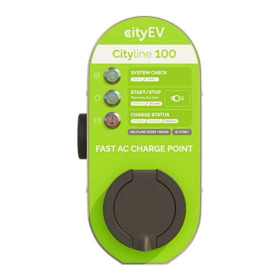
Page 5: The Cityline 100 Fast Ac Chargepoint
The maximum charge rate is programmable from 1.4KW to 8KW (6A to 32A) to allow adaption to local supply availability. The Cityline 100 can be managed by a central system and offers operators a choice of access methods, with our mobile app, fob operation or free-to-use modes. -
Page 6: Installation
Cityline 100 Installation Manual Installation The Cityline charge point can be either post mounted or wall mounted. Guidance is given below for both mounting methods. The charge point consists of two main components, the front panel which houses all the electronics, and the weatherproof back shell. -
Page 7: Post Mount Installation
Cityline 100 Installation Manual Cityline 100 Installation Manual Post Mount Installation The Cityline 100 can be mounted to the following standard column sizes using the appropriate CityEV post mount brackets: 76mm, 89mm, 114mm, 140mm, 168mm For a standard column mount installation, the following tools and consumables will be needed:... -
Page 8: Mechanical Installation
Mechanical Installation To comply with IET regulations the charge point should be installed with the charging socket positioned between 0.75M and 1.4M from the ground. The chargepoint is attached to the post using the CityEV post mount bracket. Max 1400mm... -
Page 9: Mounting The Chargepoint
Cityline 100 Installation Manual Mounting the Chargepoint 2/3/4 Position the drill jig in the desired Insert the crimp nuts using the insertion position and drill 3 x 5mm pilot holes in tool. the post. Attach post mount to post with 2 x M6 x Drill out the top pilot hole to 20mm for 20 button head screws. -
Page 10: Wall Mount Installation
Cityline 100 Installation Manual Wall Mount Installation The Cityline 100 can be mounted to any suitable flat surface using the CityEV wall plate adaptor. The following tools and consumables will be needed: Security Driver Bits 4 x suitable wall fixings... -
Page 11: Mechanical Installation
Mechanical Installation To comply with IET regulations the charge point should be installed with the charging socket positioned between 0.75M and 1.4M from the ground. The chargepoint is attached to the wall using the CityEV wall mounting plate Max 1400mm... -
Page 12: Mounting The Chargepoint
Cityline 100 Installation Manual Mounting the Chargepoint Decide on the supply cable entry position. This can either from the rear of the charge point, through the wall and mounting plate Via a conduit from the bottom of the charge point If cable access will be from the rear of the charge point, create the cable access through the wall bearing in mind that this will line up with the large hole in the top of the mounting plate. -
Page 13: Supply Connections
Cityline 100 Installation Manual Supply Connections Install the supply tails into the back shell via the rear or bottom cable gland. For 16A/20A supply and 16A charge point use 4.0mm cable. For 32A/40A supply and 32A charge point use 6mm cable. - Page 14 Cityline 100 Installation Manual MID Approved Meter Version [ Note see reference installation schematic on pages 19 & 20 ] Column, Lamp & Safevolt probe connection EV via Safevolt: > Case Earth > Earth OUT Column, Lamp & ------------------------- EV via Safevolt: Column &...
- Page 15 Cityline 100 Installation Manual Cityline 100 Installation Manual 1. Once the supply cables are connected, connect the GSM antenna cable to the SMA connector on the top of the circuit board. GSM Antenna Connection Re attach the front panel by offering the bottom of the panel first to the back shell.
-
Page 16: Safevolt Function
The Cityline 100 charge point has built-in CityEV Safevolt ® technology which provides protection in the event of a PME earthing failure and enables the Cityline 100 to be safely installed on a PME system and be fully compliant with BS7671 18 edition amendment 1. -
Page 17: Sense Probe Cable
Cityline 100 Installation Manual Cityline 100 Installation Manual The sense probe is connected via a 2-pin connector located at the bottom of the main PCB, The probe is connected to the pin marked “Probe” (Left hand connection). The charge point is delivered with a link installed between the two pins of this connector. -
Page 18: Earthing Precautions
Cityline 100 Installation Manual Sense Probe Performance Because the measurement system is high impendence the system can work with a "very poor" earth probe connection; The earth probe connection impendence can be up to 120K Ohms and still operate reliably. This will allow the probe to be installed in many situations which would be unsuitable for a safety earth TT connection. -
Page 19: Reference Installation Schematics
Reference Installation Schematics The schematic below shows the typical installation arrangement for the Cityline 100 installation. Points to note: For 3.5KW installations use a 20A 2 pole Type A RCD, 20A MCB and 4mm cable. For 7.2KW installations use a 40A 2 pole Type A RCD, 40A MCB and 6mm cable. - Page 20 Cityline 100 Installation Manual Chargepoint E-IN E-IN Lamp Supply 20A MCB* E-OUT E-IN (Not Used) 6A MCB 2 pole 30mA Type A Earth In RCD* Cut-Out Column Incoming PME Earth L N E * Alternatively, a 20A double pole RCBO can be used Supply Column &...
- Page 21 Cityline 100 Installation Manual Testing The Cityline 100 unit is initially configured to power up in "free to use" mode. That no authorisation or payment functions are enabled, and the charge point is available for EV charging and testing. This test procedure assumes the changepoint is in free to use mode as shipped and that GSM communications are enabled.
-
Page 22: Local Chargepoint Configuration
Cityline 100 Installation Manual Local Chargepoint Configuration If the charge point has an active SIM card installed and is configured to connect to the CityEV back office system, then all charge point configuration will be automatically performed by the back-office system. -
Page 23: Available Configuration Parameter Options
Cityline 100 Installation Manual Cityline 100 Installation Manual Available Configuration Parameter Options Charging Authorisation Three modes are available: 1. Always authorised, free to use. (default) 2. Always authorised, free to use but can be enabled or disabled using key fob. -
Page 24: Configuration Programming Method
Cityline 100 Installation Manual Configuration Programming Method 1. Press Start/Stop switch 2. Swipe master Key fob Middle green LED flashes 3. Within 20 seconds press start/stop switch again Top LED flashes to indicate charge authorisation mode Top LED flashes in groups to indicate currently programmed authorisation mode as follows:... - Page 25 Cityline 100 Installation Manual After 20 seconds middle LED indicates maximum charge current Middle LED flashes in groups to indicate Maximum Charging current: 1 flash = 16A 2 flashes = 32A > Press start/stop switch to change mode After 20 seconds bottom LED indicates communications mode...
- Page 26 Cityline 100 Installation Manual After 20 seconds top & bottom LEDs indicates Safevolt mode Top & Bottom LED flashes in groups to indicate Safevolt mode: 1 flash = Safevolt in line voltage sense mode earth touch voltage sensing probe mode...
- Page 27 Cityline 100 Installation Manual Keyfob Programming: Master key fobs can be used for normal charging authorisation and for charge point programming. Additionally, master key fobs can add new user key fobs to the system. User key fobs can only be used to authorise charging and cannot be used for system programming.
-
Page 28: Cityline 100 Operation
Cityline 100 Installation Manual Cityline 100 Operation Panel Indicators System Status LED Chargepoint Authorisation Status LED Charging Status LED GSM Communications Antenna Type 2 EV Connection Socket RFID Key Fob Reader Area Page 28... -
Page 29: Cityline 100 Indicator Led Functions
Cityline 100 User Operation Manual Cityline 100 Indicator LED Functions The Cityline 100 uses 3 tri-colour LEDS to indicate the charge point status, the LED functions are set out in the table below. System Status LED (1) System OK. Ready to charge Establishing communications. - Page 30 Charging Status LED (3) EV not connected EV Connected Charging in progress EV Charged EV Fault DC earth leakage trip. Not available to charge LED key: Slow Flashing Quick Flashing Page 30...
-
Page 31: Vehicle Charging Procedure
Cityline 100 User Operation Manual Vehicle Charging procedure To charge your vehicle: 1. Ensure that the charge point is ready and available for changing. This is indicated by a GREEN system check LED. 2. Connect the EV to using the appropriate cable to the type 2 EV connection socket located on the front of the unit. -
Page 32: Nfc / Qr Label Application
Cityline 100 User Operation Manual NFC / QR Label Application If the CityEV App is to be used with the chargepoint, apply the NFC/QL label to the right-hand side of the chargepoint as shown. For consistent label placing a registration mark is provided on the right-hand side of the label which should be lined up with the horizontal case join. -
Page 33: Chargepoint Measurements And Reporting
Cityline 100 User Operation Manual Chargepoint Measurements and Reporting After each charging cycle the following information will be uploaded by the charge point to the back-office system: Chargepoint ID User ID Time EV was connected Time EV started charging ... -
Page 34: Declaration Of Conformity
Cityline 100 User Operation Manual Declaration of Conformity Page 34... - Page 35 NOTES Page 35...
- Page 36 NOTES Page 36...
- Page 37 CityEV Helpline: 02393190109 support@cityev.net CityEV Ltd., Technopole, Kingston Crescent, Portsmouth, UK, PO2 8FA Page 37...
Need help?
Do you have a question about the Cityline 100 and is the answer not in the manual?
Questions and answers