Table of Contents
Advertisement
Quick Links
Advertisement
Table of Contents

Related Manuals for R&S RT-Z1M


Summary of Contents for R&S RT-Z1M
- Page 1 ® R&S RT‑Z1M High-impedance buffer amplifier Manual (B1OZ2) 1801314202 Version 05...
- Page 2 This manual describes the usage of the R&S RT-Z1M high-impedance buffer amplifier (1337.9200.02). © 2023 Rohde & Schwarz GmbH & Co. KG Muehldorfstr. 15, 81671 Muenchen, Germany Phone: +49 89 41 29 - 0 Email: info@rohde-schwarz.com Internet: www.rohde-schwarz.com Subject to change – data without tolerance limits is not binding.
-
Page 3: Table Of Contents
® Contents R&S RT‑Z1M Contents 1 Safety information..................5 2 Product description................7 Key features and key characteristics................7 Unpacking the product....................7 2.2.1 Inspecting the contents....................8 Description of the buffer amplifier................8 2.3.1 Buffer amplifier box......................9 2.3.2 Probe interface........................9 2.3.3 Dimensions of buffer amplifier and probe..............10 Accessories......................... - Page 4 ® Contents R&S RT‑Z1M Calibration interval......................18 Storage and transport....................18 Disposal........................18 6 Functional test..................20 Manual 1801.3142.02 ─ 05...
-
Page 5: Safety Information
® Safety information R&S RT‑Z1M 1 Safety information The product documentation helps you use the product safely and efficiently. Follow the instructions provided here and in the following chapters. Intended use The R&S RT‑Z1M high-impedance buffer amplifier is designed for measurements on circuits that are only indirectly connected to the mains or not connected at all. - Page 6 ® Safety information R&S RT‑Z1M ● Do not apply voltages higher than the maximum rated voltage, see the imprint on the buffer amplifier. ● When using the buffer amplifier in combination with a passive probe that can mea- sure voltages higher than the maximum rated input voltage of the buffer amplifier (e.g.
-
Page 7: Product Description
® Product description R&S RT‑Z1M Unpacking the product 2 Product description 2.1 Key features and key characteristics The R&S RT‑Z1M high-impedance buffer amplifier is an accessory for oscilloscopes that have only inputs with 50 Ω input impedance. It allows you to connect measure- ment equipment requiring a 1 MΩ... -
Page 8: Inspecting The Contents
® Product description R&S RT‑Z1M Description of the buffer amplifier ● User manual of the R&S RT‑Z1M ● R&S RT-ZP10 10:1 passive probe ● User manual of the R&S RT-ZP10 ● Accessories for R&S RT-ZP10 (delivery contents is listed in the user manual of the probe) ●... -
Page 9: Buffer Amplifier Box
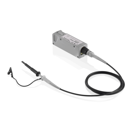
® Product description R&S RT‑Z1M Description of the buffer amplifier 1 = Buffer amplifier box 2 = R&S probe interface to connect an active probe to the buffer amplifier, and a contact ring to connect a passive probe 3 = R&S probe interface to connect the buffer amplifier to an oscilloscope 4 = Release knob 5 = R&S RT-ZP10 passive probe 2.3.1 Buffer amplifier box... -
Page 10: Dimensions Of Buffer Amplifier And Probe
® Product description R&S RT‑Z1M Accessories 2.3.3 Dimensions of buffer amplifier and probe The R&S RT‑Z1M high-impedance buffer amplifier and the R&S RT-ZP10 passive probe have the following dimensions (all values in mm): ‑ Z1M high-impedance buffer amplifier with R&S RT-ZP10 Figure 2-3: Dimensions of the R&S RT 2.4 Accessories 2.4.1 Supplied accessories... -
Page 11: Putting Into Operation
® Putting into operation R&S RT‑Z1M Connecting the buffer amplifier to the oscilloscope 3 Putting into operation Read and observe the instructions in Chapter 1, "Safety information", on page 5 before using the buffer amplifier. For your safety, follow the safety instructions delivered with your Rohde & Schwarz oscilloscope and probe, and the instructions given in the manuals of your measure- ment equipment. -
Page 12: Identification Of Buffer Amplifier And Probe
® Putting into operation R&S RT‑Z1M Disconnecting the buffer amplifier from the DUT ► To disconnect the buffer amplifier: a) Press and hold the release button (3). b) Pull the buffer amplifier away from the oscilloscope. 3.2 Identification of buffer amplifier and probe When the R&S RT‑Z1M is connected to the oscilloscope, the oscilloscope recognizes the buffer amplifier and reads out the specific parameters from the data memory of the buffer amplifier. -
Page 13: Using The Buffer Amplifier
® Putting into operation R&S RT‑Z1M Using the buffer amplifier 3.5 Using the buffer amplifier All settings of the R&S RT‑Z1M are adjusted on the oscilloscope. These settings are: ● Offset ● Input coupling ● Lowpass filter (bandwidth) ● Self-alignment The gain or attenuation of the buffer amplifier is automatically set by the oscilloscope depending on the vertical scale. -
Page 14: Analog Bandwidth
® Putting into operation R&S RT‑Z1M Using the buffer amplifier 3.5.3 Analog bandwidth The R&S RT‑Z1M features two lowpass filters of 200 MHz and 20 MHz. The filters reduce bandwidth and thus noise during the measurement. The bandwidth filter is part of the vertical settings of the channel to which the buffer amplifier is connected. -
Page 15: Typical Characteristics
® Typical characteristics R&S RT‑Z1M Step response 4 Typical characteristics The R&S RT‑Z1M high-impedance buffer amplifier has several gain or attenuation modes. The mode of the buffer amplifier, and thus the gain or attenuation, depends on the vertical scale and is set automatically by the oscilloscope to achieve optimized sys- tem behavior. - Page 16 ® Typical characteristics R&S RT‑Z1M Step response ‑ Z1M (all 7 modes) Figure 4-2: Step response of the R&S RT The rise time of a system is inversely proportional to the bandwidth. The following approximation applies: rise The minimum measurable rise time of the whole setup also depends on the bandwidth of the probe connected to the R&S RT‑Z1M, and the bandwidth of the oscilloscope.
-
Page 17: Maintenance And Service
® Maintenance and service R&S RT‑Z1M Contacting customer support 5 Maintenance and service Like all Rohde & Schwarz products, Rohde & Schwarz probes and adapters are of high quality and require only minimum service and repair. However, if service or calibration is needed, contact your Rohde &... -
Page 18: Returning For Servicing
® Maintenance and service R&S RT‑Z1M Disposal 5.3 Returning for servicing Use the original packaging to return your R&S RT‑Z1M to your Rohde & Schwarzser- vice center. A list of all service centers is available on: www.services.rohde-schwarz.com If you cannot use the original packaging, consider the following: 1. - Page 19 ® Maintenance and service R&S RT‑Z1M Disposal Figure 5-2: Labeling in line with EU directive WEEE Rohde & Schwarz has developed a disposal concept for the eco-friendly disposal or recycling of waste material. As a manufacturer, Rohde & Schwarz completely fulfills its obligation to take back and dispose of electrical and electronic waste.
- Page 20 ® Functional test R&S RT‑Z1M 6 Functional test The functional test confirms the basic operation of the R&S RT‑Z1M high-impedance buffer amplifier and the R&S RT-ZP10 passive probe using simple measurement equipment. The functional test is not suitable to verify compliance with the specifications of the R&S RT‑Z1M high-impedance buffer amplifier, because the test results are influenced by the used oscilloscope.
Need help?
Do you have a question about the RT-Z1M and is the answer not in the manual?
Questions and answers