Table of Contents
Advertisement
Quick Links
Installation Instructions
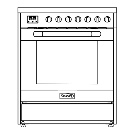
30" Free-Standing Gas Range
Model : KM-FR30G-SS
For any service-related Issues, please contact us:
Email address: support@koolmore.com
Phone Number: 718-576-6342
IMPORTANT SAFETY INSTRUCTIONS:
CAREFULLY READ THE IMPORTANT INFORMATION
REGARDING INSTALLATION, SAFETY AND
MAINTENANCE. KEEP THESE INSTRUCTIONS FOR
FUTURE REFERENCE.
Advertisement
Table of Contents

Subscribe to Our Youtube Channel
Related Manuals for KoolMore KM-FR30G-SS


Summary of Contents for KoolMore KM-FR30G-SS
- Page 1 Installation Instructions 30" Free-Standing Gas Range Model : KM-FR30G-SS For any service-related Issues, please contact us: Phone Number: 718-576-6342 Email address: support@koolmore.com IMPORTANT SAFETY INSTRUCTIONS: CAREFULLY READ THE IMPORTANT INFORMATION REGARDING INSTALLATION, SAFETY AND MAINTENANCE. KEEP THESE INSTRUCTIONS FOR FUTURE REFERENCE.
-
Page 2: Table Of Contents
TABLE OF CONTENTS RANGE SAFETY ....................3 INSTALLATION REQUIREMENTS ................. 5 Tools and Parts ....................... 5 Location Requirements ....................7 Electrical Requirements ....................11 Gas Supply Requirements ................... 12 INSTALLATION INSTRUCTIONS ................ 15 Step 1 - Unpack Range ....................15 Step 2 - Install Backsplash ................... -
Page 3: Range Safety
RANGE SAFETY Your safety and the safety of others are very important. We have provided many important safety messages in this manual and on your appliance. Always read and obey all safety messages. This is the safety alert symbol. This symbol alerts you to potential hazards that can kill or hurt you and others. - Page 4 WARNING Fire Hazard If the information in this manual is not followed exactly, a r e or explosion may result causing property damage, personal injury or death. - Do not store or use gasoline or other ammable vapors and liquids in the vicinity of this or any other appliance.
-
Page 5: Installation Requirements
State of California Proposition 65 Warnings: WARNING: This product contains one or more chemicals known to the State of California to cause cancer. WARNING: This product contains one or more chemicals known to the State of California to cause birth defects or other reproductive harm. INSTALLATION REQUIREMENTS TOOLS AND PARTS Gather the required tools and parts before starting installation. -
Page 7: Location Requirements
LOCATION REQUIREMENTS VENTILATION IMPORTANT: Observe all governing codes and ordinances. Do not obstruct fl w of combustion and ventilation air. • It is the installer’s responsibility to comply with installation clearances specified on the model/serial rating plate. The model/serial rating plate is located on the left-hand side of the oven frame. - Page 8 DIMENSIONS Product and Opening Opening dimensions shown are for 25" (64.0 cm) countertop depth, 4" (61.0 cm) base cabinet depth and 36" (91.4 cm) countertop height. 20" 24" 5.9" 5.9" 30" 30" (15 cm) (15 cm) (76 cm) (76 cm) Min.
- Page 9 DIMENSIONS Product and Opening 30" 36" 5.9" 5.9" 30" 30" (15 cm) (15 cm) (76 cm) (76 cm) Min. Min. Min. Min. Model Depth w/ D. Height to top E. Height B. Width C. Depth Size Handle of Cooktop Overall 30"...
- Page 10 Back of Range Gas Line from Range Power Cord Power Supply IMPORTANT: mounted, but an electrical outlet in the wall must be recessed to make the connection. For Direct Wiring, the electrical box should be mounted to the wall. 3" (7.6 cm) 20"...
-
Page 11: Electrical Requirements
ELECTRICAL REQUIREMENTS WARNING Electrical Shock Hazard Plug into a grounded 3 prong outlet. Do not remove the ground prong from the power cord plug. Do not use an adapter. Do not use an extension cord. Failure to do so can result in death, re or electrical shock. IMPORTANT: The range must be electrically grounded in accordance with local codes and ordinances, or in the absence of local codes, with the National Electrical Code, ANSI/NFPA 70 or Canadian Electrical Code, CSA C22.1. -
Page 12: Gas Supply Requirements
NOTE: The metal chassis of the range must be grounded in order for the control panel to work. If the metal chassis of the range is not grounded, no keypads will operate. Check with a qualified electrician if ou are in doubt as to whether the metal chassis of the range is grounded. - Page 13 LP gas conversion: IMPORTANT: Conversion must be done by a qualified service technician. No attempt shall be made to convert the appliance from the gas specified on the model/serial rating plate for use with a different gas without consulting the serving gas supplier.
- Page 14 Rigid pipe connection: The rigid pipe connection requires a combination of pipe fi tings to obtain an in-line connection to the range. The rigid pipe must be level with the range connection. All strains must be removed from the supply and fuel lines so range will be level and in line.
-
Page 15: Installation Instructions
INSTALLATION INSTRUCTIONS IMPORTANT: This appliance shall be installed only by authorized persons and in accordance with the manufacturer’s installation instructions, local gas fi ting regulations, municipal building codes, electrical wiring regulations, local water supply regulations. STEP 1 - UNPACK RANGE WARNING Excessive Weight Hazard Use two or more people to move and install range. - Page 16 NOTE: 20" model uses (2) screws and the 24" model uses (2) screws 30" model uses (2) screws and the 36" model uses (4) screws 20" 24" 30" 36" Model Backsplash -Back Edge Backsplash - Bottom Edge 3. Insert the two screws (one on each side) through the back edge of the backsplash and into the cooktop.
-
Page 17: Step 3 - Install Anti-Tip Bracket
STEP 3 - INSTALL ANTI-TIP BRACKET IMPORTANT: This insert replaces the directions for “Installing the Anti-Tip Bracket” and “Installing the Range” found in the 24" and 30" Electric Free- Standing Range Installation Instructions for Models HCR2250AES and HCR3560AES. INSTALL ANTI-TIP BRACKET WARNING Tip Over Hazard A child or adult can tip the range and be killed. - Page 18 3. Using the anti-tip bracket as a template, mark the two holes for either a Floor Wood, Floor Concrete, or Wall installation, as shown. Distance from Adjacent Cabinet (³⁄₈" to ¹⁄₂" [0.95 to 1.27 cm]) Wall Holes Concrete Floor Holes Wood Floor Holes Rear Range Foot 4.
-
Page 19: Step 4 - Make Gas Connection
STEP 4 - MAKE GAS CONNECTION WARNING Explosion Hazard Use a new CSA International approved gas supply line. Install a shut-off valve. Securely tighten all gas connections. If connected to LP, have a quali†ed person make sure gas pressure does not exceed 14" (36 cm) water column. Examples of a quali†ed person include: licensed heating personnel, authorized gas company personnel, and... - Page 20 CONNECT GAS LINE FROM GAS PRESSURE REGULATOR TO GAS SUPPLY: 1. Apply pipe-joint compound made for use with LP gas to the tapered (NPT) threads of both adapters supplied with gas line kit. 2. Attach one adapter to the gas pressure regulator and the other to the gas shutoff valve and tighten b th.
-
Page 21: Step 5 - Make Electrical Connection
STEP 5 - MAKE ELECTRICAL CONNECTION WARNING Electrical Shock Hazard Plug into a grounded 3 prong outlet. Do not remove the ground prong from the power cord plug. Do not use an adapter. Do not use an extension cord. Failure to do so can result in death, re or electrical shock. 1. -
Page 22: Step 7 - Level The Range (If Needed)
3. Slowly attempt to tilt the range forward. If you encounter immediate resistance, the range foot is engaged in the anti-tip bracket. Go to Step 8. 4. If the rear of the range lifts more than 1/2" (1.3 cm) off the floor withou resistance, stop tilting the range and lower it gently back to the floor. -
Page 23: Step 8 - Check Operation Of Electronic Ignition System
STEP 8 - CHECK OPERATION OF ELECTRONIC IGNITION SYSTEM The cooktop and oven burners use electronic igniters in place of standing pilots. When the cooktop control knob is turned to the “ICON” position, the system creates a spark to light the burner. This sparking continues, as long as the control knob is turned to “ICON.”... -
Page 24: Gas Conversion
If the low flame needs to be adjusted: Adjustment Screw Control Knob Stem 1. Light one burner and turn the control knob to the lowest setting. 2. Remove the control knob. 3. Insert a small, fla -blade screwdriver into the adjustment screw, and slowly turn the screw until the flame appea ance is correct. - Page 25 LP/PROPANE GAS CONVERSION This appliance can be used with Natural Gas or LP/Propane gas. It is shipped from the factory for use with natural gas. A kit for converting to LP gas is supplied with your cooktop. The kit is marked “FOR LP/PROPANE GAS CONVERSION”. When the cooktop is converted for liquid petroleum (LP) gas, the LP gas supply is required to provide a minimum of 10"...
- Page 26 20" & 24" Burner and Orifice Characteristic Table Orifice Pressure Rate Burner Diam. (mm) Type [i.w.c.] [BTU/h] 4" 13000 Triplering 1.08 LP (Propane) 10" 13000 1.18 4" 6000 Semi-Rapid 0.72 LP (Propane) 10" 6000 4" 3500 Auxiliary 0.56 LP (Propane) 10"...
- Page 27 24" Burner and Orifice Characteristic Table Orifice Pressure Rate Burner Diam. (mm) Type [i.w.c.] [BTU/h] 4" 18000 Triplering 1.22 LP (Propane) 10" 17000 1.29 4" 6900 Semi-Rapid LP (Propane) 10" 6900 1.05 4" 5000 Auxiliary LP (Propane) 10" 5000 1.15 4"...
- Page 28 30" Burner and Orifice Characteristic Table (M-A) Orifice Pressure Rate Burner Diam. (mm) Type [i.w.c.] [BTU/h] 4" 18000 Triplering 1.22 LP (Propane) 10" 17000 1.45 4" 8800 Rapid 0.91 LP (Propane) 10" 8800 1.29 4" 6900 Semi-Rapid LP (Propane) 10" 6900 1.05 4"...
- Page 29 30" Burner and Orifice Characteristic Table (DENFEDI) Orifice Pressure Rate Burner Diam. (mm) Type [i.w.c.] [BTU/h] 0.93+1.92 4" 18000 Triplering 0.56+1.18 LP (Propane) 10" 18000 4" 11000 Rapid 1.03 LP (Propane) 10" 11000 1.17 4" 6000 Semi-Rapid 0.75 LP (Propane) 10"...
- Page 30 36" Burner and Orifice Characteristic Table (M-A) Orifice Pressure Rate Burner Diam. (mm) Type [i.w.c.] [BTU/h] 4" 18000 Triplering 1.22 LP (Propane) 10" 17000 1.45 4" 8800 Rapid 0.91 LP (Propane) 10" 8800 1.29 4" 6900 Semi-Rapid LP (Propane) 10" 6900 4"...
- Page 31 36" Burner and Orifice Characteristic Table (DENFEDI) Orifice Pressure Rate Burner Diam. (mm) Type [i.w.c.] [BTU/h] 0.93+1.92 4" 18000 Triplering 0.56+1.18 LP (Propane) 10" 18000 4" 11000 Rapid 1.03 LP (Propane) 10" 11000 1.17 4" 6000 Semi-Rapid 6000 0.75 LP (Propane) 10"...
-
Page 32: Step 1 - Adjust The Regulator
STEP 1 - ADJUST THE REGULATOR IMPORTANT: Disconnect all electrical power, at the main circuit breaker or fuse box. Shut off the gas supp y to the range by closing the manual shut-off valve 1. Unscrew the regulator cap with the wrench. Regulator Cap 2. -
Page 33: Step 2 - Change Burner Ori Ices
4. Screw the regulator cap back into the regulator and reattach the regulator to the nipple and fla e union. STEP 2 - CHANGE BURNER ORIFICES IMPORTANT: Carefully read and observe each orifice label or correct location. See the Burner Chart earlier in this section. NOTE: First remove all orifices and then start eplacing them. -
Page 34: Step 3 - Adjust Burner Flames
Properly Seated Not Properly Seated STEP 3 - ADJUST BURNER FLAMES NOTES: • Turn all burners on highest setting and check the flames. hey should be blue in color and may have some yellow tipping at the ends of the flame when using LP gas. -
Page 35: Step 4 - Testing Flame Stability
2. Remove the control knob. 3. Insert a small, fla -blade screwdriver into the adjustment screw, and slowly turn the screw until the flame appea ance is correct. • Open the valve more if the flames a e too small or flu tered. •...
Need help?
Do you have a question about the KM-FR30G-SS and is the answer not in the manual?
Questions and answers
KM-FR30G How do I replace the igniter in the oven? Do I have to take off the rear panel of the range in order to get out the connection for the igniter?