
Subscribe to Our Youtube Channel
Related Manuals for KoolMore KM-FR36GL-SS


Summary of Contents for KoolMore KM-FR36GL-SS
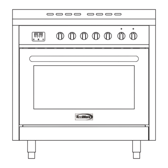
- Page 1 Installation Instructions 36" Free-Standing Gas Range with Legs Model : KM-FR36GL-SS For any service-related Issues, please contact us: Phone Number: 718-576-6342 Email address: support@koolmore.com...
- Page 2 At its sole discretion. Koolmore Supply Inc may determine to replace the product. In the event of product replacement, your appliance will be warranted for the remaining term of the original unit's warranty period.
-
Page 3: Table Of Contents
TABLE OF CONTENTS RANGE SAFETY ....................4 INSTALLATION REQUIREMENTS ................. 8 Tools and Parts ....................... 8 Location Requirements ....................10 Electrical Requirements ....................14 Gas Supply Requirements ...................19 INSTALLATION INSTRUCTIONS ................ 20 Step 1 - Unpack Range ....................20 Step 2 - Make Gas Connection ..................23 Step 3 - Make Electrical Connection ................25 Step 4 - Install Range ....................25 Step 5 - Level the Range (if needed) ................26... -
Page 4: Range Safety
RANGE SAFETY WARNING A child or adult can tip the range and be killed. Install the anti-tip device to the structure and / or the range. Verify the anti-tip device has been properly installed and engaged [state how for the two or more possible loctions]. - Page 5 Your safety and the safety of others are very important. We have provided many important safety messages in this manual and on your appliance. Always read and obey all safety messages. This is the safety alert symbol. This symbol alerts you to potential hazards that can kill or hurt you and others.
- Page 6 WARNING Fire Hazard If the information in this manual is not followed exactly, a fire or explosion may result causing property damage, personal injury or death. - Do not store or use gasoline or other ammable vapors and liquids in the vicinity of this or any other appliance. - WHAT TO DO IF YOU SMELL GAS •...
- Page 7 In the State of Massachusetts, the following installation instructions apply: • Installations and repairs must be performed by a qualified or licensed contractor, plumber, or gasfitter qualified or licensed by the State of Massachusetts. • If using a ball valve, it shall be a T-handle type. •...
-
Page 8: Installation Requirements
INSTALLATION REQUIREMENTS TOOLS AND PARTS Gather the required tools and parts before starting installation. Read and follow the instructions provided with any tools listed here. TOOLS NEEDED • • 3/8" nut driver Tape measure • • Flat-blade screwdriver 1/4" nut driver •... -
Page 10: Location Requirements
LOCATION REQUIREMENTS VENTILATION IMPORTANT: Observe all governing codes and ordinances. Do not obstruct flow of combustion and ventilation air. It is the installer’s responsibility to comply with installation clearances specified • on the model/serial rating plate. The model/serial rating plate is located on the left-hand side of the oven frame. - Page 11 DIMENSIONS Warning: Cabinets 13 in. deep and not less than the nominal width of the appliance must be installed at least 30 in. above the cooking surface. Cabinets maximum 13 in. deep may be installed on both sides of the appliance with the bottom of the cabinets at least 18 in.
- Page 12 Back of Range Gas Line from Range Power Cord Power Supply IMPORTANT: mounted, but an electrical outlet in the wall must be recessed to make the connection. For Direct Wiring, the electrical box should be mounted to the wall. 3" (7.6 cm) 20"...
- Page 13 IMPORTANT: Installation must be Figure 4 in compliance with the consumption declaration. In order to ensure 1.8” adequate ventilation, the back panel (45 mm) of the cabinet unit must be removed. Installing the oven so that it rests on two strips of wood is preferable. If the oven rests on a continuous, flat surface, there must be an aperture of at least 1 ¾”...
-
Page 14: Electrical Requirements
ELECTRICAL REQUIREMENTS WARNING Electrical Shock Hazard Plug into a grounded 3 prong outlet. Do not remove the ground prong from the power cord plug. Do not use an adapter. Do not use an extension cord. IMPORTANT: The range must be electrically grounded in accordance with local codes and ordinances, or in the absence of local codes, with the National Electrical Code, ANSI/NFPA 70 or Canadian Electrical Code, CSA C22.1. - Page 15 A copy of the above code standards can be obtained from: National Fire Protection Association 1 Batterymarch Park Quincy, MA 02169-7471 CSA International 8501 East Pleasant Valley Road Cleveland, OH 44131-5575 • A 120 volt, 60 Hz., AC only, 15-amp fused, electrical circuit is required. A time- delay fuse or circuit breaker is also recommended.
- Page 16 Wiring Diagram Electrical diagrams Caution: Label all wires prior to disconnection when servicing controls. Wiring errors can cause improper and dangerous operation. Verify proper operation after servicing. Attention: Étiqueter tous les fils avant de les débrancher pour effectuer l’entretien des régulateurs.
- Page 17 GAS SUPPLY REQUIREMENTS WARNING Explosion Hazard Use a new CSA International approved gas supply line. Install a shut-off valve. Securely tighten all gas connections. does not exceed 14" (36 cm) water column. licensed heating personnel, authorized gas company personnel, and authorized service personnel.
- Page 18 LP gas conversion: IMPORTANT: Conversion must be done by a qualified service technician. No attempt shall be made to convert the appliance from the gas specified on the model/serial rating plate for use with a different gas without consulting the serving gas supplier.
-
Page 19: Gas Supply Requirements
Rigid pipe connection: The rigid pipe connection requires a combination of pipe fittings to obtain an in-line connection to the range. The rigid pipe must be level with the range connection. All strains must be removed from the supply and fuel lines so range will be level and in line. -
Page 20: Installation Instructions
INSTALLATION INSTRUCTIONS IMPORTANT: This appliance shall be installed only by authorized persons and in accordance with the manufacturer’s installation instructions, local gas fitting regulations, municipal building codes, electrical wiring regulations, local water supply regulations. STEP 1 - UNPACK RANGE WARNING Excessive Weight Hazard Use two or more people to move and install range. - Page 21 INSTALL ANTI-TIP CHAIN A child or adult can tip the range and be killed. Install anti-tip device to range and / or struture per installation instructions. Engage the range to the anti-tip device installed to the structure Re-engage the anti-tip device if range is moved. Failure to follow these instructions can result in death or serious burns to children and adults.
- Page 22 FITTING THE ADJUSTABLE FEET The adjustable feet must be fitted to the base of thefreestanding oven before use. Rest the rear of the freestanding oven on a piece of the packaging (i.e. the polystyrene) exposing the base for the fitting of the feet. IMPORTANT! Be very careful not to damage the freestanding oven during this process.
-
Page 23: Step 2 - Make Gas Connection
STEP 2 - MAKE GAS CONNECTION WARNING Explosion Hazard Use a new CSA International approved gas supply line. Install a shut-off valve. Securely tighten all gas connections. If connected to LP, have a quali ed person make sure gas pressure does not exceed 14"... - Page 24 CONNECT GAS LINE FROM GAS PRESSURE REGULATOR TO GAS SUPPLY: 1. Apply pipe-joint compound made for use with LP gas to the tapered (NPT) threads of both adapters supplied with gas line kit. 2. Attach one adapter to the gas pressure regulator and the other to the gas shutoff valve and tighten both.
-
Page 25: Step 3 - Make Electrical Connection
STEP 3 - MAKE ELECTRICAL CONNECTION WARNING Electrical Shock Hazard Plug into a grounded 3 prong outlet. Do not remove the ground prong from the power cord plug. Do not use an adapter. Do not use an extension cord. Failure to do so can result in death, re or electrical shock. 1. -
Page 26: Step 5 - Level The Range (If Needed)
3. Slowly attempt to tilt the range forward. If you encounter immediate resistance, the range foot is engaged in the anti-tip bracket. Go to Step 8. 4. If the rear of the range lifts more than 1/2" (1.3 cm) off the floor without resistance, stop tilting the range and lower it gently back to the floor. -
Page 27: Step 6 - Check Operation Of Electronic Ignition System
STEP 6 - CHECK OPERATION OF ELECTRONIC IGNITION SYSTEM The cooktop and oven burners use electronic igniters in place of standing pilots. When the cooktop control knob is turned to the “ICON” position, the system creates a spark to light the burner. This sparking continues, as long as the control knob is turned to “ICON.”... - Page 28 If the low flame needs to be adjusted: Adjustment Screw Control Knob Stem 1. Light one burner and turn the control knob to the lowest setting. 2. Remove the control knob. 3. Insert a small, flat-blade screwdriver into the adjustment screw, and slowly turn the screw until the flame appearance is correct.
- Page 29 Ignite the burner of oven 1. Set the working time in timer firstly; 2. Push and turn the knob to ignite; 3. Observe whether the burner is burning through the glass window. If burners do not light properly: 1. Check if the timer have been set? 2.
- Page 30 LP/PROPANE GAS CONVERSION This appliance can be used with Natural Gas or LP/Propane gas. It is shipped from the factory for use with natural gas. A kit for converting to LP gas is supplied with your cooktop. The kit is marked “FOR LP/PROPANE GAS CONVERSION”. When the cooktop is converted for liquid petroleum (LP) gas, the LP gas supply is required to provide a minimum of 10"...
- Page 31 36" Burner and Orifice Characteristic Table (M-A) Manifold Orifice Rate Pressure Burner Diam. (mm) Type [i.w.c.] [BTU/h] 4" 18000 Triplering 1.22 LP (Propane) 10" 17000 1.45 4" 8800 Rapid 0.91 LP (Propane) 10" 8800 1.29 4" 6900 Semi-Rapid LP (Propane) 10"...
-
Page 32: Gas Conversion
STEP 1 - ADJUST THE REGULATOR IMPORTANT: Disconnect all electrical power, at the main circuit breaker or fuse box. Shut off the gas supply to the range by closing the manual shut-off valve. 1. Unscrew the regulator cap with the wrench. Regulator Cap 2. -
Page 33: Step 2 - Change Burner Ori Ices
4. Screw the regulator cap back into the regulator and reattach the regulator to the STEP 2 - CHANGE BURNER ORIFICES IMPORTANT: the Burner Chart earlier in this section. NOTE: possibility that some may not be replaced. 1. Remove the burner grates, burner caps and burner heads. Triple Ring Burner Auxiliary Burner Semi-Rapid Burner... -
Page 34: Step 3 - Adjust Burner Flames
Properly Seated Not Properly Seated STEP 3 - ADJUST BURNER FLAMES NOTES: Turn all burners on highest setting and check the flames. They should be blue in • color and may have some yellow tipping at the ends of the flame when using LP gas. -
Page 35: Step 4 - Testing Flame Stability
2. Remove the control knob. 3. Insert a small, flat-blade screwdriver into the adjustment screw, and slowly turn the screw until the flame appearance is correct. • Open the valve more if the flames are too small or fluttered. Close the valve more if the flames are too large. •...
Need help?
Do you have a question about the KM-FR36GL-SS and is the answer not in the manual?
Questions and answers