Table of Contents
Advertisement
Quick Links
EN
Installation and Maintenance guide
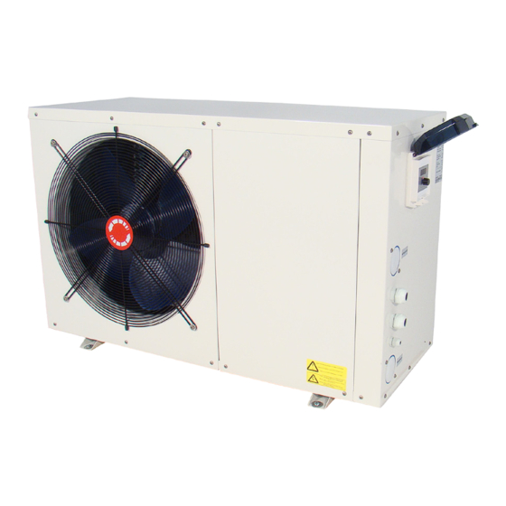
R12/R15/R20/R30/R30-3P/R50-3P
______________________________________________________________________________________________
Rev. 2016.1
Gullberg & Jansson AB | Hortensiagatan 7 | SE - 256 68 Helsingborg
Tel: +46 (0) 42 311 15 00 | Fax: +46 (0) 42 34 02 10 | E-mail: info@gullbergjansson.se | www.gullbergjansson.se
Advertisement
Table of Contents

Related Manuals for Gullberg & Jansson R12


Summary of Contents for Gullberg & Jansson R12
- Page 1 Installation and Maintenance guide R12/R15/R20/R30/R30-3P/R50-3P ______________________________________________________________________________________________ Rev. 2016.1 Gullberg & Jansson AB | Hortensiagatan 7 | SE - 256 68 Helsingborg Tel: +46 (0) 42 311 15 00 | Fax: +46 (0) 42 34 02 10 | E-mail: info@gullbergjansson.se | www.gullbergjansson.se...
- Page 2 Preface Congratulations on your purchase of a pool heat pump from Gullberg & Jansson AB. We hope it meets your expectations and provides you with many years of energy efficient heating. In this Installation and Maintenance Guide you can read how installation, operation, service and maintenance are to be performed to ensure correct function.
-
Page 3: Table Of Contents
Service and support Technical specification Miscellaneous Checklist installation Connection key PC1001 Guarantee conditions Wiring diagram Safety Regulations One-phase connection Three-phase connection R12/R15/R20/R30/R30-3P Installation Component placement Outline diagram Technical data Dimensions and connections Positioning the unit R50-3P Set up Distance to the pool... -
Page 4: General Information
General information This chapter provides background information about the pool heat pumps covered in this Installation and Maintenance Guide. Important information, guarantee conditions and safety instructions are also presented here. This chapter is intended for both users and installation engineers. Product description outdoor temperature and the temperature of the pool water. -
Page 5: Component Part And Accessories
General information Component part and accessories Large amounts of melt and condensation water can be discharged during defrosting and operation. Consequently, it Main unit – GJPASRW-12/15/20/30/50 is important to provide good drainage and run-off. Installation accessories The units must stand freely so that air is not prevented to •... -
Page 6: Miscellaneous
General information Miscellaneous Guarantee conditions The unit may only be repaired by a qualified installation The component parts of the system must be transported, engineer or an accredited workshop. Original spare parts stored and installed in accordance with the provisions set out must be used for repairs. -
Page 7: Installation
Installation A comprehensive installation description is provided in this chapter. This chapter is primarily intended for installation engineers, but can also be read by the end user to increase his/her knowledge. Outline diagram Chlorinator POOL Sand filter Circulation pump Refer to the labels on the unit before connecting the inlet and outlet. Positioning the unit Set up The pool heat pump will work ideally under the following... -
Page 8: Distance To The Pool
Installation Distance to the pool Adjusting the bypass Correct adjust of the bypass can be done in different ways. The pool heat pump is normally installed in connection to One of the easiest ways can be summarized as follows: the pool’s purification system to minimise pipe routing. If the Open all the valves pipes are insulated heat loses will be minimal provided that the overall pipe length is less than 30 metres (pool water in... -
Page 9: Electrical Installation
Installation Electrical installation Starting up the unit The electrical connection is made to the pool heat pump’s In order to heat the pool or spa water, the pool’s circulation junction box located behind the front panel. A working pump must start and water needs to circulate through the switch (with or without a fuse) must be connected and be heat exchanger. -
Page 10: Use And Operation
Use and operation Description of LED controls How to change operating parameters Shut down the unit by pressing in the knob. A description of the LED display is given below. All parameters are set at the factory and do not need to be Select the parameter between 0-9 by rotating the knob. -
Page 11: How You Select The Operating Mode
Use and operation Parameter 7: Automatic restart on Parameter 8: (0 = Cooling mode / 1 Parameter 9: External pump. (0 = power failure. (0 = No / 1 = Yes) = Heating mode or cooling mode / Always running / 1 = Running at 2 = Not used / 3 = Heating mode) the same time as the compressor) If, for example, you wish to change the required temperature in heating, press and hold the knob for 2 seconds and then... -
Page 12: Maintenance, Service And Fault Tracing
Maintenance, service and fault tracing Winter drainage 5 It is a good idea to clean the heat exchanger to promote good function and energy savings. This can easily be done with winter drainage. Flush the heat exchanger It is extremely important to remember to winter drain using e.g. -
Page 13: Fault Charting Table
Maintenance, service and fault tracing Fault charting table Operating disturbance Cause Action The heat pump is in standby Press the ON/OFF button. mode. Change the operating mode The heat pump is in cooling to Heating mode as set out mode. in the section 4. -
Page 14: Technical Specification
Technical specification Connection key PC1001 AI06 OUT3 OUT1 OUT2 AI05 OUT4 AI04 PC1001 OUT5 AI03 AC-N AI02 AI01 CN16 Label Description OUT1 Control signal to compressor relay (230 VAC) OUT2 Control signal to circulation pump (230 VAC) OUT3 Control signal to four way valve (230 VAC) OUT4 Control signal to fan motor (230 VAC) OUT5... -
Page 15: Wiring Diagram
AI02 Ambient temperature AI01 COMP Compressor Compressor heater Coil temperature CN16 Exhaust temperature Fan motor Flow switch LED indicator High pressure switch Inlet water temperature 230V Contactor of compressor Low pressure switch Outlet water temperature Transformer 4 way valve R12/R15/R20/R30... -
Page 16: Three-Phase Connection
Technical specification Wiring diagram Three-phase connection L1 L2 L3 TO POWER SUPPLY 400 VAC / 50 Hz L1(A) L2(B) L1 L2 L3 L3(C) COMP1 AI06 OUT3 L1 L2 L3 OUT1 OUT2 AI05 OUT4 PC1001 AI04 OUT5 AI03 AC-N Ambient temperature AI02 Compressor COMP... -
Page 17: R12/R15/R20/R30/R30-3P
Technical specification GJPASRW-12/15/20/30 Component placement Component placement Galvanized steel casing - top Compressor Protective net - back High pressure switch Galvanized steel casing - left Low pressure switch Fan motor bracket Flow switch Protective net - left Galvanized steel casing - right Fan motor LED-controller Impeller... -
Page 18: Technical Data
Technical specification Technical data Model GJPASRW-12 GJPASRW-15 GJPASRW-20 GJPASRW-30 Heating output 13.5 Input power 0.95 Heating capacity 15 - 25 20 - 30 30 - 45 45 - 75 Operating voltage 230 VAC 1-phase 50 Hz 400 VAC Operating current 4.18 5.23 7.50... -
Page 19: R50-3P
Technical specification GJPASRW-50 Component placement Component placement Liquid separator Protective net - back Steel casing - bottom PVC-bend 90 deg Steel casing - service hatch Drainage Protective fence Heat exchanger Steel casing - front Flow switch Compressor Phase relay Impeller Casing connector Fan motor bracket Steel casing - right... -
Page 20: Technical Data 100
Technical specification Technical data Model GJPASRW-50 Heating output Input power Heating capacity 60 - 115 Operating voltage 400 VAC 3-phase 50 Hz Operating current Fuse size Compressor Scroll compressor Refrigerant amount (R410a) Fan consumption Rated air flow 4600 Noise level (1 m) dB(A) Water connection 50 mm...
Need help?
Do you have a question about the R12 and is the answer not in the manual?
Questions and answers