Table of Contents
Advertisement
Quick Links
Advertisement
Chapters
Table of Contents

Related Manuals for Tsuruga 471B


Summary of Contents for Tsuruga 471B
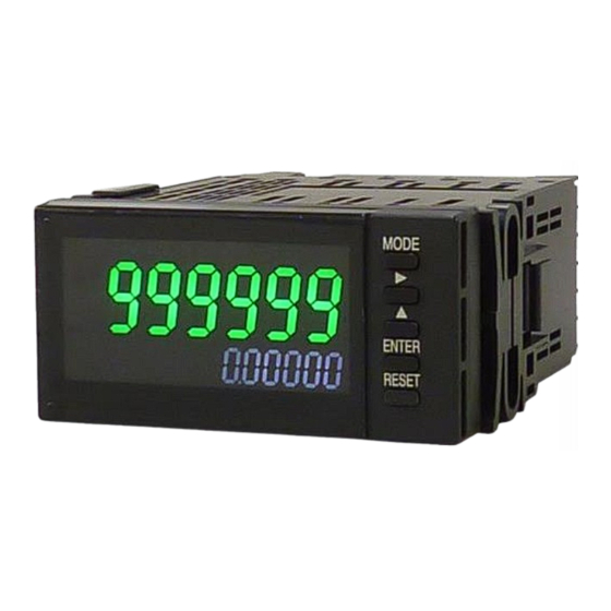
- Page 1 Panel meter with totalized function Pulse input 471B Quick Manual...
-
Page 2: Table Of Contents
Contents Introduction ····················································· 1 About this booklet ········································································· 1 Precautions ·················································································· 1 Installation Precautions ·································································· 2 Nomenclature ··················································· 3 Operation Panel ············································································ 3 Rear Panel ···················································································· 5 Installation ······················································· 6 Installation Conditions ···································································· 6 Accessories··················································································· 6 Mounting Method ·········································································· 7 Dismounting ·················································································... -
Page 3: Introduction
Introduction About this booklet Thank you for purchasing our digital panel meter 471B. Before use of the product, read this quick manual carefully and thoroughly, and keep it available for routine reference. The following symbol marks are used in this quick manual for the safety use of the product. -
Page 4: Installation Precautions
Introduction(contd.) Installation Precautions For the safe use of this product, users must follow the following caution. ! Caution If the product is installed inside the cabinet, provision for the proper heat dissipation should be done to prevent the temperature to exceed more than 50 ℃... -
Page 5: Nomenclature
Nomenclature Operation Panel ⑧ Comparative display ① Display 1 (AL1~AL4) ② Display 1 Over ⑨ SET Display MODE OVER TOTAL ⑩ Setting key INST ENTER RESET ⑪ Reset key kW h kW ⑤ INST ④ Display 2 ⑥ Display1 Unit ③... - Page 6 Nomenclature(contd.) Name Function Setting key During measurement mode:Change to Setting ⑩ mode、Adjustment mode MODE During setting mode:Change to each code No. During measurement mode:Invalid During setting mode:Digit selection of setting value During measurement mode:Invalid(Except when switching to diagnostic mode) ▲ During setting mode:Change of setting value During measurement mode:Invalid During setting mode:Set value changed to saved...
-
Page 7: Rear Panel
Rear Panel Name Function ⑫ Terminal A1~A6 Sensor power supply, Input、P.O output terminal ⑬ BCD OUTPUT Open collector NPN transistor output CONNECTOR Terminal RS-232C B1~5:RS-232C communication, B6: Vacant terminal Terminal RS-485 B1:+, B2:-, B4~5: Terminating resistance, B3, B6:Vacant terminal ⑭ Terminal C1~C6 C1~3:Control input terminal, C4:Vacant terminal、... -
Page 8: Installation
Terminal block IP00 Accessories Make sure that the following things beside the main body part are included. 471B main unit Bracket 2 pcs. Waterproof packing Quick Manual (This booklet) (For the model with RS-232C or RS-485, exclusive quick manual is included.) ... -
Page 9: Mounting Method
Mounting Method Mounting pitch More than 30mm Panel cutout dimensions: 92 +0.8 × 45 +0.6 Panel thickness: 0.6 to 3.5mm (Degree of protection IP65) 3.6 to 10mm (Degree of protection IP20) If the material of the panel is aluminum, it may More than 130mm be deformed due to its weak strength. -
Page 10: Dismounting
Installation(contd.) Dismounting By extending with fingers the lever outward by about 1mm, as shown in the bracket lock releasing figure, the lever lock can be released. Keep extending the lever outward, slide the bracket backward of the main unit, and remove it from the ditch. -
Page 11: Wiring Method
Wiring Method Remove the terminal base cover of the rear side terminal and conduct the wiring. Make sure that the terminal base cover is attached after wiring. If both options of comparison output and analog output are used, first complete the wiring of the comparison output and then start the wiring of analog output. - Page 12 Installation(contd.) About the crimp terminal Direction of crimp terminal Recommended crimp terminal:V1.25-FS3 Unit: mm (Made of Fuji Terminal Industry Co.,Ltd) Ext. diameter of covered cable:Max.φ3.3 Terminal screw:M3 5.85 Crimp terminal: Refer figure at the right 18.25 ! Caution For the C column and D column terminal blocks, apply one crimp terminal per one terminal block.
-
Page 13: Terminal Layout And Explanation
Do not use as relay terminal etc. Term Term ! Caution Replacement of the units by customers NC:Vacant terminal themselves may cause the damage of the equipment and Tsuruga Electric Corporation may not be able to respond in this case. - Page 14 Installation(contd.) Power supply connection Connect the power supply at Terminal No.E1-E3. AC power supply Power supply voltage is written on the Terminal nameplate at the time of product shipment. ○AC power supply GND for power supply AC100 to 240V 50/60Hz permissible range AC 90 to 250V DC power supply ○DC power supply...
- Page 15 Connection of input signal Power supply for the sensor is connected from terminal No.A1-A2. If the power supply of sensor is applied from external sources, the connection of terminal No. A1 will not be required. When sensor power source is not used, A1 will be vacant and do not used it for other purpose. ○...
- Page 16 P / L RESET or P/L Less than 10mA Photocouplers Swich D.COM 471B internal parts Connection of Analog output The analog output is can be obtained from the Terminal No.C5-C6. Allowable load resistance should be connected within the specified range.
- Page 17 No.18(Gray) No.36(Blue) Upper cable No.1~18 Lower cable No.19~36 Accessory: Cable (5808-05) 2m Connector (8822E-036-171-F, Kel Corp.) Electrical schematic diagram DC power supply 471B DC24V 16 BCD_LATCH Transistor output unit Transistor output unit 17 SEL 15 OUTPUT Transistor output unit ENABLE...
-
Page 18: Usage Of Function Code
Usage of Function Code Function code list ●Display functions Code No. Function Display 1 Setting range Default value Key protection KEY. OFF, ON Totalized pulse coefficient 9999E-0 to 0001E-9 0001E-0 TPLS Converted value of 1000E-0 to 0001E-6 0001E-0 IPLS instant pulse Unit of instant time 2(hour), 1(minute), 0(second) 0(second) -
Page 19: Setting Method Of Code No
●RS-232C, RS-485 output function Code No. Display 1 Setting range Default value Function Baud rate 4800,9600,19200bps 9600bps BAUD. Parity non(none), odd(odd no.), even(even no.) non(none) PARIT BCC switching ON, OFF Device number RS.NO. 0 to 99 Setting method of code No. This is the basic input method of function code. -
Page 20: Function Setting Method
Usage of Function Code(contd.) Function setting method The following is an example of the input function setting. Please refer this page when changing to the setting other than factory setting value. Please continue the operation of the function setting after referring Code No. setting method only. Code No.00『Key protection』... - Page 21 Code No.02 『 Converted value of instant Code No.03『Unit of instant time』 pulse』 The magnification of a pulse can be set with The unit of instant time can be set arbitrarily. maximum 4 digits of mantissa and exponent 1 This is the time unit to indicate the digit in code No.02.
- Page 22 Usage of Function Code(contd.) Code No.06『Instantaneous display cycle』 Code No.07『Totalized decimal point』 Code No.08『Instant decimal point』 Select and set instantaneous display cycle from The decimal point at an arbitrary position can 100ms,1s,5s be lit up. The decimal point is not linked with the totalizing constant setting (it does not Setting range:100ms(0), 1s(1), 5s(2) possess weight).
- Page 23 Code No.09『Initial totalizing value』 Code No.10『Display 1 switching』 Initial totalizing value is set if in case the Select display 1 for either totalized display or display value of the counting start is specified. instantaneous display. Setting range:0 to 999999 Setting range:0,Display 1:Instantaneous display Display 2:Totalized display 1,Display 1:Totalized display Display 2:Instantaneous display...
-
Page 24: Specification
Specification Model Configuration 471B- ③ ⑤ ① ② ④ Power Sensor PhotoMOS Analog Digital compare supply power output output output supply Addition No. Function Symbol contents AC100 to 240V ① Power supply DC24V DC110V No power to sensor Sensor power ②... - Page 25 Decimal point Optional selection (External control not allowed) Over display Display 1 OVER Light up during over(Red color ) Totalizer : Display 1 When 999999 exceeds, Light up OVER (Light up until RESET input) Internal counter counts up to 99999999 Starts count from 0 when 99999999 exceeds Instant : When 999999 exceeds, Light up OVER, ------...
- Page 26 Optional output PhotoMOS compare output This is the setting change method of photoMOS compare output. operate following the setting code No. mentioned on page 17. Code No.41『AL1 Comparative value 』 Code No.45『Batch switching』 Code No.42『AL2 Comparative value 』 Code No.43『AL3 Comparative value 』 Code No.44『AL4 Comparative value 』...
- Page 27 Code No.46『AL3 Output width』 Code No.48『Auto reset』 Code No.47『AL4 Output width』 During batching of AL 3 to 4, select the time During batching of AL3 to 4, when AL4 auto width with one shot of specified output. reset is ON, reset is done when totalized value Note) Continuous output is turned OFF by becomes AL4.
-
Page 28: Analog Output
Optional output(contd.) Analog output Refer page 9 for "Wiring method" of this manual for the connector arrangement. The measurement input and the analog output are insulated. Accuracy Instantaneous ± 0.1 % of SPAN at 23℃ ± 5℃ Totalized ± 0.5 % of SPAN at 23℃ ± 5℃ Output cycle Approx. - Page 29 Function setting This is the setting change method of analog output. Operate following the setting code No. mentioned on page 17. Code No.75『Analog output switching』 Code No.79『Full scale of analog output』 Select analog output of instantaneous or During analog output, the display equivalent to totalizer.
-
Page 30: Bcd Output (Digital Output)
Optional output(contd.) BCD output (Digital output) Refer to "Wiring method" from this manual on page 9 for the connector arrangement. The measurement input and the BCD output are insulated. Output Open collector Sink type, Contact capacity DC30V 10mA Data BCD 6 digits Lower 6 digits totalizer or output of instantaneous value Over(OVER) Totalizer :When 999999 exceeds, output become ON (Output becomes... - Page 32 Tsuruga Electric Corporation Osaka Headquarters 1-3-23, Minamisumiyoshi, Sumiyoshi-ku, Osaka, Japan 〒558-0041 TEL 81-6 -6692-6700, FAX 81-6 -6609- 8115 E-mail: ft.info@tsuruga.co.jp Yokohama office 1-29-15, Shinyokohama, Kohoku-ku, Yokohama, Kanagawa, Japan 〒222-0033 Tokyo Office 5-25-16, Higashigotanda, Shinagawa-ku, Tokyo, Japan 〒141-0022 Nagoya Office Sun Park Higashi Betsuin Bld. 2F 5-19, Oicho, Naka-ku, Nagoya, Aichi, Japan 〒460-0015...
- Page 33 Panel meter with totalized function Pulse input 471B RS-232C Output RS-485 Quick Manual...
- Page 34 Contents 内容 About this booklet ·············································· 1 Model name for communication output ··············· 1 Connector arrangement and connection method · 2 RS-232C ············································································· 2 RS-485··············································································· 2 Function code ····················································· 3 Communication command (RS-232C, RS-485 common) ·· 4 Instructions about the comment ············································ 4 Command/Response ···························································...
-
Page 35: About This Booklet
About this booklet Thank you for purchasing Tsuruga product. This is the quick optional manual for RS-232C, RS-485 output. Refer the quick manual of the main body for cautions beside the usage the RS-232C, RS-485 output, installation, operation etc. Before use of the product, read this quick manual carefully and thoroughly, and keep it available for routine reference. -
Page 36: Connector Arrangement And Connection Method
Connector arrangement and connection method RS-232C 471B DTE side (computer side) Pin No. Terminal Signal Signal name name D Sub 25 Pin D Sub 9 Pin Shielded wire Optional:RS-232C cable 2 m(Model 5858-10) RS-485 Terminal Signal Description name + "+" Indicates non-inverted output -... -
Page 37: Function Code
SI-30, Manufactured by LINEEYE CO. Ltd., Function code Communication setting is done by front key operation. When changing to a setting other than the factory set value, please refer "Usage of Function Code" of the Quick Manual of model 471B on page 16. Baud rate Baud rate can be selected. -
Page 38: Communication Command (Rs-232C, Rs-485 Common)
There have been some cases of not being able to response the command even 3 seconds after the power supply reached the rated voltage because of initialization of 471B. As there may be cases of responding undefined data too, it is highly advised to communicate only after it has reached to rated voltage more than 3 seconds. -
Page 39: Command/Response
Response during the command error Device No.:00 Exit code (BCC) (02H) (30H) (30H) (50H) (03H) Response during the setting time. Device No.:00 Exit code (BCC) (02H) (30H) (30H) (42H) (03H) Command/Response ◆ Measurement commend Command :TREA Totalized value of requested data Response :Response to TREAD(Totalized value of measurement data)... - Page 40 20H 2BH 31H 2EH 30H 30H 30H 30H 30H 45H 2BH 33H 03H Reading of the device information Command :IDNT? Reading of the device information Response :Response to IDNT 471B, No. 888-101 [Model No., Software registration No. (Tsuruga)] Command frame: ETX (BCC) ? Device No.:00 Response:...
- Page 41 Reading of judgment Command :ALAR Reading of Judgment Response :Response to ALARM ※It provides the status of comparison output. In the example, it is the sum of the weights of AL1 and AL2(01+02=03). Please, refer the Judgment command on page 11 for the detail reference. 01(AL1 output)...
- Page 42 Reading of control command The contents set by control command is read out. Command :RLAT Reading of Latch Response :Response to RLATCH 0(OFF) Command frame: ETX (BCC) Device No.:00 30H 52H 4CH 41H 54H 43H 48H 03H Response: ETX (BCC) Device No.:00 Exit code 30H 03H...
- Page 43 Memory initialization Setting data resets to the value during the factory shipment time. But, the transmission speed, parity, BCC switch and device number cannot brought bring to default value. Command :DEFA Response :Exit code Command frame: ETX (BCC) Device No.:00 30H 44H 45H 46H 41H 55H 4CH Response:...
-
Page 44: Command List
Command list Required setting Required setting command command Setting command Command Response Command frame Response Setting item, range Totalized pulse RC01 0001E-0 WC01 0001E-1 0001E-1 9999E-0 to 0001E-9 coefficient Converted value of RC02 0000E-0 WC02 1000E-2 1000E-2 1000E-0 to 0001E-6 instant pulse Unit of instant time RC03... - Page 45 Required measurement data command Command of measurement data Command Response Totalized value TREA _+1.0000000E+3 measurement data Instantaneous value IREA _+1.00000E+3 measurement data Judgment command Judgment request command (Result output of Command Response Item currently judgment) AL1 to 4 ALAR Output status Weight of data Required control Specified control command command...
- Page 46 MEMO...
- Page 48 Tsuruga Electric Corporation Osaka Headquarters 1-3-23, Minamisumiyoshi, Sumiyoshi-ku, Osaka, Japan 〒558-0041 TEL 81-6 -6692-6700, FAX 81-6 -6609- 8115 E-mail: ft.info@tsuruga.co.jp Yokohama office 1-29-15, Shinyokohama, Kohoku-ku, Yokohama, Kanagawa, Japan 〒222-0033 Tokyo Office 5-25-16, Higashigotanda, Shinagawa-ku, Tokyo, Japan 〒141-0022 Nagoya Office Sun Park Higashi Betsuin Bld. 2F 5-19, Oicho, Naka-ku, Nagoya, Aichi, Japan 〒460-0015...
Need help?
Do you have a question about the 471B and is the answer not in the manual?
Questions and answers