Table of Contents
Advertisement
Quick Links
Advertisement
Chapters
Table of Contents

Related Manuals for Tsuruga 471C


Summary of Contents for Tsuruga 471C
- Page 1 Tachometer 471C Quick Manual...
-
Page 2: Table Of Contents
Teaching function ········································································ 23 Adjustment of analog output (Option) ················································· 24 Restore to the factory setting ································································ 25 Specification ··················································· 26 Option Output ················································· 28 PhotoMOS compare output ··························································· 28 Analog output ············································································· 32 BCD output (Digital output) ·························································· 34 471C... -
Page 3: Introduction
This model is tachometer. Signal from rotor is displayed as rotation speed. About this booklet Thank you for purchasing our Tachometer 471C. Before use of the product, read this quick manual carefully and thoroughly, and keep it available for routine reference. -
Page 4: Installation Precautions
*Wet place (rain, water drops), direct sunlight *Place having high temperature, humidity, dust and corrosive gases *Place having excessive noise, waves, static electricity *Place having lots of vibration and shock Store the product in the specified temperature range between -20℃ to 65℃. 471C... -
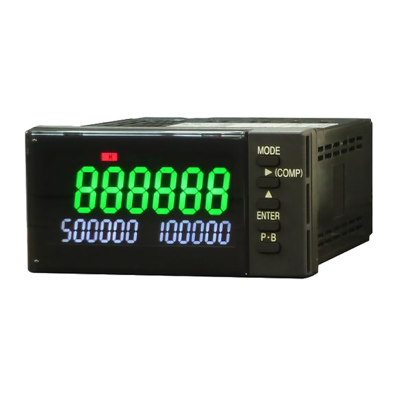
Page 5: Nomenclature
Either bottom value or comparator value set by customer can be displayed. Display color: White ⑦ Unit Pasting position of Unit sticker ⑧ Comparative The comparison status of the comparison output is display displayed. ⑨ SET Display Light on during setting mode. 471C... - Page 6 0 1 2 3 4 5 6 7 8 9 . A B C D M N O T U V W X A B C D E F G H I J K L M N O P Q R S T U V W X Y Z 471C...
-
Page 7: Rear Panel
C5, C6: Analog output terminals ⑮ Terminal D1 D6: HH, H, L and LL output terminals ⑯ Terminal E1 E1, E3: Power supply terminals E5: Ground terminal E2, E4, E6: Vacant terminals ※ ⑬, ⑭ and ⑮ are option specification 471C... -
Page 8: Installation
IP00 Accessories Make sure that the following items are included with product supplied. ・471C main unit ・Bracket 2pcs. ・Waterproof packing ・Quick Manual (This booklet) (For the model with RS-232C or RS-485, exclusive quick manual is included.) ・Unit Sticker ・Connector (2m with flat cable) (In case of BCD Output model) -
Page 9: Mounting Method
② ① Panel to mount Waterproof packing ! Caution When the bracket is pressed by minus screwdriver, press it to the direction as shown in arrow ②. The pressing of other part may cause the damage of bracket. 471C... -
Page 10: Dismounting
Extend the lever about Enlarged view of 1mm and releases the bracket inside lock Lever ! Caution The extension of the lever or the stress to it by metallic piece like screwdriver for a long time may damage the lever. 471C... -
Page 11: Wiring Method
In case that the noise is frequently occurred, it will be effective to store the product in the shielded housing or to insert the power source line filter or insulated transformer. 471C... - Page 12 Do not wire the parallel connection, using two crimp terminals (overlaying) at the same terminal location. It stresses the internal PCB and may cause the failure or trouble. As for the A column and E column terminal blocks, up to two crimp terminals per terminal location are acceptable. 471C...
-
Page 13: Terminal Layout And Explanation
Term Term NC: Non contact terminal Do not use it. ! Caution ・Replacement of the above terminal units by customers themselves is prohibited because it may be the cause the damage of the product. 471C... - Page 14 In this case, take care for the ground terminal not to touch other input terminals, as it is charged with neutral electric potential of power source voltage. 471C...
- Page 15 Voltage pulse output NPN open collector sensor sensor SENSOR SENSOR 4.0~30V SIG1 SIG1 0~1.5V SIG2 SIG2 ! Caution If sensor power supply terminal A1 is accidentally short-circuited with COM terminal A2, it may cause malfunction of the product. 471C...
- Page 16 M.SEL4 M.SEL1/2/4 Less than 10mA Photocouplers Switch M.COM 471C internal Connection of analog output The analog output can be obtained from the Terminal No.C5-C6. Use analog output within the specified range of allowable load resistance. (Refer Page 26『Model Configuration』 )...
- Page 17 Connector (8822E-036-171-F, Kel Corp.) Electrical schematic diagram DC power supply 471C DC24V 16 BCD_LATCH Transistor output unit 17 OUTPUT Transistor output unit ENABLE DC24V 15 OVER Darington 4 8×10 3 4×10 2 2×10 1 1×10 18,35,36DATA COM (0V) Controller side 471C...
-
Page 18: Usage Of Function Code
●Option BCD output, Analog output Code Default Function Display1 Setting range № Value BCD logic switching 0: Negative, 1: Positive 0: Negative B.PN 0 (Last 4digits), 1 (Middle 4 digits), Digit selection D.SEL. 2 (First 4 digits) Full-scale 0 to 9999 9999 A.FUL. 471C... -
Page 19: Setting Method Of Code No
Again, if P・B key is pressed more than 1 second, the setting value which under changing process becomes invalid and returns ,▲ to measuring process. Select the Code № MODE Confirm To function setting 471C... -
Page 20: Function Setting Method
1sec. MODE Displays of 1sec. current setting current setting ENTER MODE 1sec. ENTER MODE 1sec. ,▲ ENTER Change 1sec. ▲ MODE mantissa portion Change the position of exponent portion MODE ENTER 1sec. ,▲ ENTER Change 1sec. MODE exponent portion 471C... - Page 21 1sec. (Item setting (Set number) ENTER ENTER MODE Displays of 1sec. MODE Displays of 1sec. current setting current setting ENTER ENTER MODE 1sec. MODE 1sec. ▲ ,▲ Change of setting ENTER Change of setting ENTER MODE 1sec. MODE 1sec. 471C...
- Page 22 MODE MODE MODE 1sec. 1sec. ENTER ENTER MODE Displays of MODE Displays of 1sec. 1sec. current setting current setting ENTER ENTER MODE MODE 1sec. 1sec. ,▲ ,▲ Change Change ENTER ENTER of setting of setting MODE MODE 1sec. 1sec. 471C...
- Page 23 Code No.01 to 09. The detail description of the setting ranges are omitted here. Please perform the other setting when necessary referring the Function Code List mentioned on Page 16. 471C...
-
Page 24: Usable Operation
SE T During setting, if 'P.B' key is pressed for more than 1 sec, new setting value becomes invalid and returns to measuring operation. Note: This function cannot be used when Key-protection is valid. To use this function, cancel Key-protection. 471C... -
Page 25: Teaching Function
1 sec. To use this function, cancel Set the decimal point Key-protection. (Displayed point is set) ▲ During setting, if 'P.B' key is pressed for more than 1 sec, new setting value becomes invalid and returns to measuring operation. 471C... -
Page 26: Adjustment Of Analog Output (Option)
Count down ▲ Count up Adjust output by multi-meter etc. Analog rated output Adjustment point 0~ 5V 0~10V 1~ 5V 20mA 4~20mA Note: This function can not be used, when Key-protection is valid. To use this function, cancel Key-protection. 471C... -
Page 27: Restore To The Factory Setting
5 sec. MO DE ENTER RESET If Enter is released, setting returns to factory default value. ※ By doing this, the setting range of Function code (Code No.01~83) and 『Adjustment of Analog Output(Option)』 returns to the factory setting. 471C... -
Page 28: Specification
Specification Model configuration 471C- ① ② ③ ④ Power PhotoMOS Analog Digital compare supply output output output Addition No. Function Symbol Contents AC100 to 240V ① Power supply DC24V PhotoMOS No output ② compare output 2 4 photoMOS Relays (HH, H, L, LL) - Page 29 -9 -0 f:Input frequency, α: Scale value 00001×10 to 99999×10 Display accuracy ± (0.008% + 1digit) at 23℃ ± 5℃ 45 to 75%RH Power supply line 1000V(AC power supply) mixed noise Sensor power supply DC12V ± 10% 80mA 471C...
- Page 30 MODE 1sec. MODE MODE 1sec. ENTER ENTER MODE Displays of 1sec. Displays of MODE 1sec. current setting current setting ENTER ENTER MODE 1sec. MODE 1sec. ▲ ,▲ Change Change ENTER ENTER of setting MODE of setting 1sec. MODE 1sec. 471C...
- Page 31 Chenge the memory No. MODE ENTER Displays of MODE 1sec. current setting ENTER MODE Display of current 1sec. comparison values. ENTER MODE 1sec. ENTER MODE 1sec. ,▲ Change ENTER of setting MODE 1sec. ,▲ Change the ENTER comparison values. MODE 1sec. 471C...
- Page 32 MODE MODE 1sec. MODE 1sec. ENTER ENTER Displays of MODE 1sec. Displays of MODE 1sec. current setting current setting ENTER ENTER MODE 1sec. MODE 1sec. ,▲ ▲ Change ENTER Change ENTER of setting MODE 1sec. of setting MODE 1sec. 471C...
- Page 33 Change from NG to GO. Mode To measurment To code No. setting Setting operation Code №55 ENTER (Item setting) MODE MODE 1sec. ENTER Displays of MODE 1sec. current setting ENTER MODE 1sec. ▲ Change ENTER of setting MODE 1sec. 471C...
-
Page 34: Analog Output
Select the digit of output data Selection of Display1 and setting mode can be selected either one type of first 4 digits or middle 4 digits or last 4 digits from 6 digit display . Output Scaling Full scale setting range 0000 to 9999 471C... - Page 35 1sec. (Item setting) (Set numbers) ENTER ENTER Displays of MODE Displays of MODE 1sec. 1sec. current setting current setting ENTER ENTER MODE MODE 1sec. 1sec. ▲ ,▲ Change Change ENTER ENTER of setting of setting MODE MODE 1sec. 1sec. 471C...
-
Page 36: Bcd Output (Digital Output)
When data enable pin is shorted with DATA COM pin or set to L level, data (OVER INCLUDED) becomes OFF state, SYNC output is prohibited, and the connect to the system data bus becomes easy. (Display is not retained). Accessory:BCD Cable 2m(Model 5808-05) 471C... - Page 37 Change from 0(Negative logic) to 1 (Positive logic) . To measurment To code No. setting Mode operation Code №70 Setting ENTER MODE MODE 1sec. (Item setting) ENTER Displays of MODE 1sec. current setting ENTER MODE 1sec. ▲ Change ENTER of setting MODE 1sec. 471C...
- Page 38 Memo: 471C...
- Page 39 471C...
- Page 40 Tsuruga Electric Corporation Osaka Headquarters 1-3-23, Minamisumiyoshi, Sumiyoshi-ku, Osaka, Japan, 558-0041 TEL 81-6 -6692-6700, FAX 81-6 -6609- 8115 E-mail: ft.info@tsuruga.co.jp Yokohama office 1-29-15, Shinyokohama, Kohoku-ku, Yokohama, Kanagawa, Japan, 222-0033 Tokyo Office 5-25-16, Higashigotanda, Shinagawa-ku, Tokyo, Japan, 141-0022 Nagoya Office Sun Park Higashi Betsuin Bld. 2F...
- Page 41 Tachometer 471C RS-232C Output RS-485 Quick Manual...
- Page 42 Contents 内容 About this booklet ······································ 1 Model name for communication output ············· 1 Connector arrangement and connection method ·················· 2 RS-232C ············································································· 2 RS-485 ··············································································· 2 Function code ············································· 3 Communication command (RS-232C, RS-485 common) ··········· 4 Instructions about the comment ············································ 4 Command/Response ···························································...
-
Page 43: About This Booklet
About this booklet Thank you for purchasing Tsuruga product. This is the quick optional manual for RS-232C, RS-485 output. Refer the quick manual of the main body for cautions beside the usage the RS-232C, RS-485 output, installation, operation etc. Before use of the product, read this quick manual carefully and thoroughly, and keep it available for routine reference. -
Page 44: Connector Arrangement And Connection Method
DTE side (computer side) Pin No. Signal Signal Terminal name name D Sub 25 Pin D Sub 9 Pin Shielded wire Optional:RS-232C cable 2 m(Model 5858-10) 471C D Sub 9P Terminal WIRE COLOR Signal Signal Pin No. ORANGE,BLACK YELLOW,BLACK ORANGE,RED... -
Page 45: Function Code
Communication setting is done by front key operation. When changing to a setting other than the factory set value, please refer " Setting method of code No." of the Quick Manual of model 471C on page 17. Baud rate Baud rate can be selected. -
Page 46: Communication Command (Rs-232C, Rs-485 Common)
There have been some cases of not being able to response the command even 3 seconds after the power supply reached the rated voltage because of initialization of 471C. As there may be cases of responding undefined data too, it is highly advised to communicate only after it has reached to rated voltage more than 3 seconds. -
Page 47: Command/Response
Response during the command error Device No.:00 Exit code (BCC) (02H) (30H) (30H) (50H) (03H) Response during the setting time. Device No.:00 Exit code (BCC) (02H) (30H) (30H) (42H) (03H) Command/Response ◆ Measurement command Command :RMREa Current value of requested data Response :Response to RMREAD ◆... - Page 48 Reading of the device information Command :IDNT? Reading of the device information Response :Response to IDNT 471C, No. 949-100 [Model No., Software registration No. (Tsuruga)] Command frame: ETX (BCC) ? Device No.:00 Response: Device No.:00 Exit code 34H 37H 31H 43H 2CH ETX (BCC) 1...
- Page 49 Setting of data setting NOTE)When setting value of input frequency filter is changed during the measurement process, measurement is stopped. The measurement can be started again after completion required setting parameter. Command :WC41_002000 HH comparison value setting (HH comparison value set to 002000) Response :Response to WC41_002000 002000 Command frame:...
-
Page 50: Command List
Command list Required setting Specified setting command command Setting command Command Response Command frame Response Setting item, Range 999999 Scale α RC01 999999E-0 WC01 999999E-1 000001~999999 0(0), 1(0.0), 2(0.00), Decimal point RC02 WC02 1 3(0.000),4(0.0000), 5(0.00000) 0(0.02kHz), 1(10kHz), Input frequency filter RC03 WC03 1 2(30kHz),3(100kHz) Display cycle... - Page 51 Required measurement data command Command of measurement data Command Response Measurement data RMREa _+1.00000E+3 Judgment command Judgment request command (Result output of Command Response Item currently judgment) HH, H, L, LL ALAR Output status Weight of data Required control command Specified control command Memory control command...
- Page 52 Tsuruga Electric Corporation Osaka Headquarters 1-3-23, Minamisumiyoshi, Sumiyoshi-ku, Osaka, Japan, 558-0041 TEL 81-6 -6692-6700, FAX 81-6 -6609- 8115 E-mail: ft.info@tsuruga.co.jp Yokohama office 1-29-15, Shinyokohama, Kohoku-ku, Yokohama, Kanagawa, Japan, 222-0033 Tokyo Office 5-25-16, Higashigotanda, Shinagawa-ku, Tokyo, Japan, 141-0022 Nagoya Office Sun Park Higashi Betsuin Bld. 2F...
Need help?
Do you have a question about the 471C and is the answer not in the manual?
Questions and answers