Table of Contents
Advertisement
O
M
PERATOR'S
ANUAL
Models
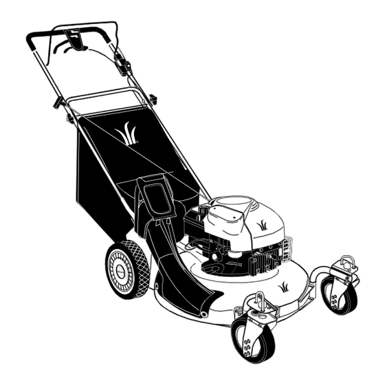
LC 215
LC 215E
Model Shown: LC 215
IMPORTANT: READ SAFETY RULES AND INSTRUCTIONS CAREFULLY
Warning:
This unit is equipped with an internal combustion engine and should not be used on or near any unimproved forest-
covered, brush-covered or grass-covered land unless the engine's exhaust system is equipped with a spark arrester meeting
applicable local or state laws (if any). If a spark arrester is used, it should be maintained in effective working order by the operator.
In the State of California the above is required by law (Section 4442 of the California Public Resources Code). Other states may have
similar laws. Federal laws apply on federal lands. A spark arrester for the muffler is available through your nearest engine authorized
service dealer or contact the service department, P.O. Box 361131 Cleveland, Ohio 44136-9722.
WHITE OUTDOOR PRODUCTS COMPANY P.O. BOX 361131 CLEVELAND, OHIO 44136-9722
PRINTED IN U.S.A.
FORM NO. 770-10182
(10/98)
Advertisement
Table of Contents

Related Manuals for White LC 215


Summary of Contents for White LC 215
- Page 1 Federal laws apply on federal lands. A spark arrester for the muffler is available through your nearest engine authorized service dealer or contact the service department, P.O. Box 361131 Cleveland, Ohio 44136-9722. WHITE OUTDOOR PRODUCTS COMPANY P.O. BOX 361131 CLEVELAND, OHIO 44136-9722 PRINTED IN U.S.A.
-
Page 2: Section 2: Calling Warranty Service
Before you start assembling the mower for its first use, please locate its model plate and copy the information on to this operator’s manual. The information on the model plate is very important if you need help from your White Outdoor dealer. -
Page 3: Section 3: Important Safe Operation Practices
SECTION 3: IMPORTANT SAFE OPERATION PRACTICES WARNING: THIS SYMBOL POINTS OUT IMPORTANT SAFETY INSTRUCTIONS WHICH, IF NOT FOLLOWED, COULD ENDANGER THE PERSONAL SAFETY AND/OR PROPERTY OF YOURSELF AND OTHERS. READ AND FOLLOW ALL INSTRUCTIONS IN THIS MANUAL BEFORE ATTEMPTING TO OPERATE YOUR LAWN MOWER. FAILURE TO COMPLY WITH THESE INSTRUCTIONS MAY RESULT IN PERSONAL INJURY. - Page 4 DO NOT: • Never operate the mower in wet grass. Always be sure of your footing. A slip and fall can cause • Do near drop-offs, ditches serious personal injury. Keep a firm hold on the embankments. The operator could lose footing or handle and walk, never run.
- Page 5 • Before cleaning, repairing, or inspecting, make thoroughly inspect the mower for any damage. certain the blade and all moving parts have Repair the damage before starting and operating stopped. Disconnect the spark plug wire, and keep the mower. the wire away from the spark plug to prevent •...
- Page 6 USE THIS PAGE AS A GUIDE TO DETERMINE SLOPES WHERE YOU MAY NOT OPERATE SAFELY. SIGHT AND HOLD THIS LEVEL WITH A VERTICAL TREE A POWER POLE A CORNER OF A BUILDING OR A FENCE POST 15° WARNING Do not mow on inclines with a slope in excess of 15 degrees (a rise of approximately 2-1/2 feet every 10 feet). A riding mower could overturn and cause serious injury.
-
Page 7: Section 5: Unpacking Instructions
SECTION 5: UNPACKING INSTRUCTIONS REMOVE UNIT FROM CARTON • Remove staples, break glue on top flaps, or cut tape at carton end and peel along top flap to open carton. • Remove loose parts if included with unit (i.e., owner’s manual, etc.). •... - Page 8 Step 4. Raise complete handle assembly until it clicks Step 3. Tighten wing nuts. into place. Make sure not to kink the control cables. HERE Handle Assembly Step 5. Pinch lower handle against mounting bracket Step 7. Attach control cables to handle with cable ties with pliers.
-
Page 9: Section 7: Controls
SECTION 7: CONTROLS Blade Control Handle Cutting Height Adjustment Lever Shift Lever Front Wheel Drive Clutch Control Caster Locks Recoil Starter Front Wheel Height Adjuster Figure 4 BLADE CONTROL HANDLE The blade control handle is located on the upper handle of the mower. See Figure 4. The blade control handle must be depressed in order to start and operate the unit. -
Page 10: Section 8: Operation
SHIFT LEVER The shift lever is located on the drive clutch control housing on the upper handle. See Figure 4. This lever is used to select the forward speed of the mower. When changing speed selection, release the drive clutch control. NOTE: Move the shift lever only when the engine is running. - Page 11 Battery Pack Charger Lead Charger Plug Figure 5 To charge the battery, (1) remove the protective cap from the end of the battery pack lead; (2) plug charger lead into battery pack lead; and (3) insert battery charger plug into 120 volt standard household outlet. See Figure 5. It is very important to follow this order of action for proper charging of the battery.
- Page 12 NEUTRAL ADJUSTMENT TEST To perform the NEUTRAL ADJUSTMENT TESTS, answer the following questions after having started the mower and engaged the drive clutch control. • With the engine OFF and the drive clutch control released, push mower forward and pull it backward. Does it move freely? •...
- Page 13 Step 3. Lift chute door and slide bag onto adapter. Top of bag rests on wire bracket that extends between the handles. Bagging Adaptor Chute Door Mulching Baffle Side-Discharge Chute EMPTYING YOUR GRASS BAG Lift grass bag from the bagging adaptor using the lower handle. While holding the lower handle, lift up the rear section of the grass bag.
-
Page 14: Section 9: Adjustments
SECTION 9: ADJUSTMENTS WARNING: Do not at any time make any adjustment to lawn mower without first stopping engine and disconnecting spark plug wire. CUTTING HEIGHT ADJUSTMENT The rear wheel cutting height adjustment lever is located above the left rear wheel. To adjust the cutting height, pull the lever out and away from the mower. - Page 15 • The mower’s drive wheels hesitate with the drive clutch engaged. To resolve the above problems, rotate the adjustment wheel with your fingers: clockwise to tighten the cable and counter-clockwise to loosen the cable. See Figure 8. Bottom View Adjustment Wheel Figure 8 Note:...
-
Page 16: Section 10: Maintenance
SECTION 10: MAINTENANCE WARNING: Be sure to disconnect and ground the spark plug wire before performing any repairs or maintenance. NOTE: When tipping the unit, empty the fuel tank and keep the engine with the discharge chute side up. Never tip the mower more than 90 degrees and do not leave the mower tipped for any length of time. - Page 17 WARNING: Periodically inspect the blade adapter for cracks, especially if you strike a foreign object. Replace when necessary. When sharpening the blade, follow the original angle of grind as a guide. It is extremely important that each cutting edge receives an equal amount of grinding to prevent an unbalanced blade. An unbalanced blade will cause excessive vibration when rotating at high speeds.
- Page 18 DRIVE BELT REMOVAL AND REPLACEMENT Step 1. Disconnect the spark plug wire and ground it Step 7. Remove the hex bolt holding the transmission against the engine. to the mower housing. Step 2. Drain the fuel tank or place a piece of plastic Rear Height Adjustment Lever beneath the cap to prevent gasoline leakage.
- Page 19 Step 13. Squeeze the belt together and push belt Step 14. Place the new belt over the transmission forward. Press the control arm inward towards the pulley. Start the belt in pulley groove and rotate deck and remove the six speed cable from the pulley until belt is seated in transmission pulley.
- Page 20 Step 21. Pinch belt together so that it is not in the Step 22. Pivot the control arm back to its original pulley groove, and the lower pulley can be position and reinstall the six-speed cable into the pushed towards the engine. slot.
-
Page 21: Section 11: Lubrication
SECTION 11: LUBRICATION WARNING: Always stop engine and disconnect spark plug wire before cleaning, lubricating or doing any kind of work on the lawn mower. Blade Control Handle LUBRICATE Wheels Caster Assembly SEE ENGINE MANUAL Figure 10 Blade Control: Lubricate the pivot points on the blade control handle and the brake cable at least once a season with light oil. -
Page 22: Section 13: Trouble Shooting Guide
SECTION 13: TROUBLE SHOOTING GUIDE Trouble Possible Cause(s) Corrective Action Engine fails to start Blade control handle disengaged. Engage blade control handle. Spark plug wire disconnected. Connect wire to spark plug. Throttle control lever not in correct Move throttle lever to FAST position. starting position. -
Page 24: Section 15: Parts List
SECTION 15: PARTS LIST Transmission Assembly for Reference only Pulley Assembly for Reference only... - Page 25 Ref. Ref. Part No. Description Part No. Description 710-0134 Scr. Carr. 1/4-20 x .62 682-9024 Caster Bracket Assembly: RH 710-0654A Scr. TT:3/8-18:1.00 682-9026 Caster Bracket Assembly: LH 710-0703 Carriage Scr. 1/4-20 x .750 711-1146 Caster Axle .374 Dia x 2.50” 712-0397 Wing Nut 1/4-20 736-0232...
- Page 26 Model LC 215E only 42 41...
- Page 27 Model LC 215E only Ref. Part No. Description Ref. No. Part No. Description 710-1174 Bolt Cur. Carr. 5/16-18 x 2.0 749-0907A Lower Handle 714-0104 Cotter Pin .072 x 1.12 Lg. 631-0071 Grassbag Cover 720-0241 Knob Assembly 5/16-18 747-0939 Pivot Rod 726-0240 Strap 4.3”...
- Page 28 Model LC 215 only...
- Page 29 Model LC 215 only Ref. Ref. Part No. Description Part No. Description 710-1174 Bolt Cur. Carr. 5/16-18 x 2.0 731-0905A Lower Control Housing 714-0104 Cotter Pin .072 x 1.12 Lg. 731-0906 Cable Mounting Cap 720-0241 Wingknob 5/16-18 731-0620 Control Lever 726-0240 Strap 4.3 Lg.
- Page 30 Multi-Speed Pulley Assembly Ref. Part No. Description 746-0939 Speed Selector Cable, 53” 656-0613 Multi-speed Pulley Assembly 710-0167 Carriage Bolt, 1/4-20 x. 5 710-1652 Self-tapping Screw, 1/4-20 x .625 711-1114 Pivot Shaft 712-0287 Nut, 1/4-20 732-0807 LH Torsion Spring 736-0270 Bell Washer, .265 x .75 x .062 736-0329 Lock Washer, 1/4 736-0526...
- Page 31 Transmission Assembly: 618-0263A Ref. Part No. Description 712-3025 Hx. Jam Nut, 5/16-24 736-0425 Bell Wash. .325 x .930 x .045 756-0656 Pulley 736-3084 Fl. Wash. .510 x 1.120 x .060 712-0896 Hx. Jam Nut , 1/4-28 782-7598 Belt Keeper 741-0600 Bearing 750-1050 Flange Spacer...
- Page 32 5. The provisions as set forth in this warranty failures will be covered if caused by defects in provide the sole and exclusive remedy of White material or workmanship. Normal wear parts are Outdoor Products Company’s obligations arising defined as belts, blades, blade adapters, grass from the sales of its products.
Need help?
Do you have a question about the LC 215 and is the answer not in the manual?
Questions and answers