Table of Contents

Summary of Contents for QED Shape Coil
- Page 1 Operator’s Manual Shape Coil/Shape Coil W For Canon 1.5T and 3.0T MRI Systems Model Canon Model # Shape Coil (1.5T) MJAB-207A Q7000198 Shape Coil W (1.5T) MJAB-217A Shape Coil (3.0T) MJAB-202A Q7000199 Shape Coil W (3.0T) MJAB-212A...
- Page 2 • Damage due to changes or modifications made to the product. In no event shall QED be liable for the following: • Damage loss or problems caused by relocation, modification, or repair performed by personnel explicitly authorized by QED.
-
Page 3: About This Manual
MRI system user manual and safety manual prior to operation of the product. This manual does not include instructions or safety information on equipment not provided by QED, such as the MRI system. Please consult the MRI system manufacturer for information regarding non-QED equipment. -
Page 4: Table Of Contents
Chapter 1 – Introduction ......................... 5 Description..........................5 Operating Environment and Compatibility................5 User Profile ..........................5 Patient Information ........................5 Chapter 2 – Shape Coil Components ......................6 Chapter 3 – Safety ........................... 7 Symbol Glossary ........................7 Indications ..........................8 Contraindications ........................8 Precautions .......................... -
Page 5: Chapter 1 - Introduction
The received signals are amplified and transmitted to the MRI system, where they are processed into tomographic images by the computer. The Shape Coil is used to examine general human anatomy, such as torso, pelvis, joints, bones and extremities. -
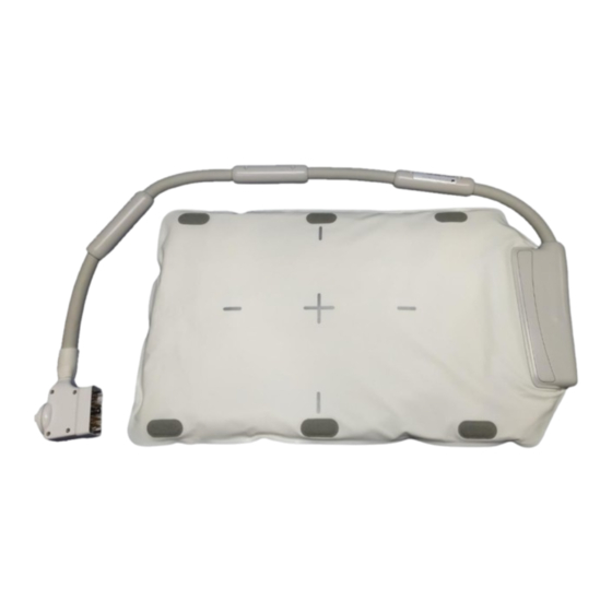
Page 6: Chapter 2 - Shape Coil Components
Chapter 2 – Shape Coil Components The Shape Coil is shipped with the parts shown below. Upon receipt, please ensure that all parts are included in the shipment. Please contact your Canon Medical Systems representative for replacement or replenishment of any accessories listed here. -
Page 7: Chapter 3 - Safety
Chapter 3 – Safety This section describes the general precautions and safety information that must be observed when this coil is used. Before using the coil, review the safety information in the MRI system operation manual for a full list of safety considerations. CAUTION 3.1 Symbol Glossary Symbol... -
Page 8: Indications
RF coil when a high- frequency magnetic field is transmitted. 3.2 Indications The Shape Coil is intended for use with Canon 1.5T or 3.0T MR systems to produce diagnostic images of general human anatomy that can be interpreted by a trained physician. 3.3 Contraindications None. -
Page 9: Cautions - Rf Coil
Patients with an inability to maintain reliable communications (for example, young children) are at increased risk of burn injury because they may not be able to notify the operator of heat or pain due to excessive heating and tissue damage. Patients with loss of feeling in any body part are at increased risk of burn injury because they may not be able to notify the operator of heat or pain due to excessive heating and tissue damage. - Page 10 body part that may form a loop. A high-frequency current may form and burns may occur. Separate the patient from the gantry inner wall by at least 10 mm using foam pads. Separate the patient from the RF coil cable by at least 10 mm using foam pads. Separate the RF coil cable from the gantry inner wall by at least 10 mm using foam pads.
-
Page 11: Cautions - Shape Coil
MR system can be used to ensure suitable spacing when placed between the RF coil and the gantry inner wall. MR System Pads That Can be used to Separate Shape Coil from Gantry Wall W300, D80, T20mm pad... - Page 12 Do not route the coil cable along the inner surface of the gantry in the circumferential direction. Doing so will cause induction current to flow in the cable, resulting in heating of the cable. Do not fold the coil by 180 near the case of the coil (as shown in the figure below). Doing so will apply excessive stress to the folded part of the coil, possibly damaging the coil.
-
Page 13: Emergency Procedures
3.7 Emergency Procedures In case of an emergency during the scan, stop the scan immediately, remove the patient from the room, and obtain medical assistance, if necessary. If a serious incident occurs in the EU, it should be reported to the manufacturer and the Competent Authority of the Member State in which the user facility is established. -
Page 14: Chapter 4 - Quality Assurance
Coil Phantom Part number 10-L copper sulfate phantom 2 Shape Coil BSM41-3176 The procedure for performing the image test without using the automatic SNR measurement tool is described below. (1) In this order, place the mat, phantom holder 2 (supplied with the system), and phantoms on the couchtop as shown in the figure below. - Page 15 (4) Secure the coil to the phantoms using the belt supplied with the system. Place the belt in a position that is not at the center of the coil so that the center of the coil is visible for alignment with the positioning projector. (5) Adjust the position of the coil so that the positioning projector beam is aligned with the center of the coil and then send the coil to the center of the gantry.
- Page 16 (8) Set the parameters for the sequence as specified below. FE_slt: Setting change is not required. (The set value of each parameter is described in the table below.) Change from default setting Parameter Set value required 35 35 cm 256 ...
- Page 17 FE_Map: Change the FOV to 35 cm 35 cm. Other setting changes are not required. (The set value of each parameter is described in the table below.) Change from default setting Parameter Set value required 35 35 cm ...
- Page 18 1 mm Plane Axial Encode direction 15 ms Flip/Flop 90/180 When the couchtop is moved with phantoms placed on the couchtop, wait approximately 5 minutes to allow the liquid in the phantoms to stabilize before starting the image test. If scanning is started before the liquid in the phantoms stabilizes, the resulting sensitivity nonuniformity in the image causes incorrect measurement of the SNR.
- Page 19 3. The images displayed with an even-numbered scan ID in the Image Matrix window are intermediate images. (11) Set the signal ROI and noise ROI as shown in the figure below. Now, record the mean signal value (mean value) of the signal ROI and the noise variance (Noise SD value) of the noise ROI in section 1 of the installation quality check sheet.
- Page 20 Position AP direction : Position free from the influence of the flow in the encode direction in the signal area (12) Calculate the SNR using the formula below. SNR calculation Signal value (mean) correction value k SNR = Noise value (SD) Phantom temperature...
-
Page 21: Phantom Image Test - 3.0T Mri System
Coil Phantom Part number 10-L oil phantom 2 Shape Coil BSM41-4885 The procedure for performing the image test without using the automatic SNR measurement tool is described below. (1) Place the system mat and phantoms on the couchtop as shown in the figure below. At this time, place the phantoms so that their bases are in contact with each other. - Page 22 (2) Connect the coil connector to the connector port at the head end of the couchtop. (3) Position the coil so that the center of the coil is over the border between the two phantoms. The crosshair marked on the coil main unit indicates the center of the coil. (4) Secure the coil to the phantoms using the belt supplied with the system.
- Page 23 operation button, move the couchtop to a position where the couchtop position indicator on the gantry operating panel reads 200. (6) Register the patient. Enter 170 cm for the height and 60 kg for the weight. (7) Select "Typical PAS" → "Coil QA" and click [Other]. Select the following sequences in the PAS "Other"...
- Page 24 (8) Set the parameters for the sequence as specified below. FE_slt: Setting change is not required. (The set value of each parameter is described in the table below.) Change from default setting Parameter Set value required 35 cm 35 cm 256 ...
- Page 25 FFE_Map: Change the FOV to 35 cm 35 cm. Other setting changes are not required. (The set value of each parameter is described in the table below.) Change from default setting Parameter Set value required 35 cm 35 cm ...
- Page 26 Other setting changes are not required. (The set value of each parameter is described in the table below.) Change from default setting Parameter Set value required 35 cm 35 cm 256 256 Matrix No Wrap (PE) 1.0 / (RO) 2.0 200 ms ...
- Page 27 (9) Start scanning using any of the above sequences. Now, record the RF Level and TGC value (TGC RFOut ratio:x.xxxxxx ) displayed in the Acquisition window. Record the TCG value that is displayed after the RF Level. When recording the TGC value and RF level, round three decimal places to two decimal places.
- Page 28 3. The images displayed with an even-numbered scan ID in the Image Matrix window are intermediate images. (11) Display the center slice of the acquired image and set the signal ROI and noise ROIs as shown in the figure below. Now, record the mean signal value (mean value) of the signal ROI and the noise variance (Noise SD value) of the noise ROIs.
- Page 29 (12) Calculate the SNR using the formula below. SNR calculation Signal value (mean) SNR = Noise value (SD) * Noise value (SD) is average of two Noise ROIs SD values. (13) Obtain the SNR for the acquired images and confirm the measurement SNR is pass or fail the specification for section 1.
-
Page 30: Chapter 5 - Coil Setup And Use
This section describes how to connect two Shape Coils and how to secure the Shape Coil to the patient if the coil could slide off the patient and cause coil misalignment. Handle this coil carefully. If the coil is dropped, it may be damaged. - Page 31 Connecting Two Shape Coils - Vertical 31 | P a g e 6000921 Rev. 1...
-
Page 32: Securing The Coil To The Patient (Optional)
When imaging is performed using two coils, attach the coils so that their cables do not come into contact with each other. Correct Attachment Incorrect Attachment 5.1.2 Securing the Coil to the Patient (Optional) When coil misalignment may be caused by the coil’s sliding to one side, the hook-and-loop fastener strap supplied with the coil may be used to secure the coil to the patient. -
Page 33: Patient Positioning And Scanning
Examples of Hook-and-Loop Strap Placement Options (2) Wrap the belt supplied with the system around the patient and coil. Attach the belt to the hook-and-loop strap. Examples of System Belt Placement Options Ensure that the positioning and retention force do not cause discomfort. 5.2 Patient Positioning and Scanning This RF coil is intended to be used for imaging of general human anatomy. -
Page 34: Patient Positioning For Trunk Imaging
The coil can be placed in the gantry in any orientation. At this time, be sure not to drop the coil. Doing so may injure the patient. When imaging the trunk, it is possible to use two coils in combination. Imaging Area of Shape Coil Center of the coil Imaging area... - Page 35 Trunk imaging (lateral position, coil placed Trunk imaging (lateral position, coil placed in across the patient): Used for imaging of the line with the patient): Used for imaging over trunk of patients who are difficult to set in the an extensive range of the trunk, such as for supine position, such as pregnant patients visualization of the spine or blood vessels of patients who are difficult to set in the supine...
- Page 36 Separate the RF coil from the gantry inner wall by CAUTION at least 50 mm using foam pads before and during imaging. When imaging is performed using two coils, set up the coils so that their cables do not come into contact with each other per Section 5.1.1. CAUTION Do not set the coil under the trunk of the patient.
- Page 37 (7) Operate the MRI system to send the patient and coil into the gantry. (8) Enter the scan conditions, referring to the operation manual for the MRI system. The coil name is "Shape Coil" and its abbreviation (displayed in the coil section selection window) is "SHP".
-
Page 38: Patient Positioning For Arm Imaging
CAUTION and burn injury may result. 1. When scanning with this coil, use the PAS set apart for "Shape Coil". If using other sequences, image quality is not guaranteed. If other sequences must be scanned, use this coil with the intensity correction "RX/TX Correction plus". - Page 39 Positioning Patient and Coil for Arm Imaging Arm imaging (supine position, coil set in line with the arm): Used for imaging of arm joints and long bones Separate the RF coil from the gantry inner wall by CAUTION at least 50 mm using foam pads before and during imaging.
- Page 40 (5) Connect the coil connector to the connector port of the couch using the information for the systems shown below. Lock the connector. Vantage Orian 1.5T: All the coil connector ports can be used for this coil. (A1, A2, A3, A4, A5, A6, A7) Vantage Galan 3T, Vantage Centurian 3T: All the coil connector ports can be used.
-
Page 41: Patient Positioning For Leg Imaging
CAUTION and burn injury may result. 1. When scanning with this coil, use the PAS set apart for "Shape Coil". If using other sequences, image quality is not guaranteed. If other sequences must be scanned, use this coil with the intensity correction "RX/TX Correction plus". - Page 42 When setting the coil, be sure not to drop it. Doing so may injure the patient. When imaging the legs, it is possible to use two coils in combination. Imaging Area of Shape Coil Center of the coil Imaging area...
- Page 43 Leg imaging (supine position, coil wrapped around Leg imaging (supine position, coils placed across the leg): Used for imaging of leg joints. the legs): Used for imaging over an extensive range, such as for visualization of blood vessels in the lower extremities. Separate the RF coil from the gantry inner wall by CAUTION at least 50 mm using foam pads before and during...
- Page 44 (5) Connect the coil connector to the connector port of the couch using the information for the systems shown below. Lock the connector. Vantage Orian 1.5T: All the coil connector ports can be used for this coil. (A1, A2, A3, A4, A5, A6, A7) Vantage Galan 3T, Vantage Centurian 3T: All the coil connector ports can be used.
- Page 45 CAUTION and burn injury may result. 1. When scanning with this coil, use the PAS set apart for "Shape Coil". If using other sequences, image quality is not guaranteed. If other sequences must be scanned, use this coil with the intensity correction "RX/TX Correction plus".
-
Page 46: Chapter 6 - Cleaning, Maintenance, Service, And Disposal
Chapter 6 – Cleaning, Maintenance, Service, and Disposal 6.1 Cleaning the RF Coil 1. Do not pour cleaning solution directly onto the coil or accessories. 2. Do not sterilize the coil or accessories. CAUTION 3. Do not apply cleaning solution to electrical contacts. 4. -
Page 47: Expected Service Life
6.5 Expected Service Life This RF coil is designed for an expected service life of at least 6 years under normal usage conditions. The coil is safe to use beyond the expected service life as long as information in the Safety section is followed and Quality Assurance tests pass. -
Page 48: Chapter 7 - Guidance And Manufacturer's Declaration - Electromagnetic Compatibility (Emc)
Chapter 7 – Guidance and Manufacturer’s Declaration – Electromagnetic Compatibility (EMC) This coil requires special attention regarding EMC and must be installed and used in accordance with the EMC guidelines provided in this manual. Only use the RF coil in the environment specified below;... -
Page 49: Electromagnetic Emission
7.3 Electromagnetic Emission The RF coil can only function when connected to the MRI system, which is contained within an RF-shielded environment. Therefore, IEC 60601-1-2 clause 7 regarding electromagnetic emission does not apply. 7.4 Electromagnetic Immunity This RF coil complies with IEC 60601-1-2 clause 8 when used in the specified electromagnetic environment. - Page 50 Manufacturer: Quality Electrodynamics, LLC. (QED) 6655 Beta Drive, Suite 100 Mayfield Village, OH 44143 U.S.A. www.qualityelectrodynamics.com Authorized Representative in Europe: Importer - EU: EMERGO EUROPE Canon Medical Systems Europe B.V. Westervoortsedijk 60 (CMSE) 6827 AT Arnhem Up to 2023-07-30: Zilverstraat 1, 2718 RP...
Need help?
Do you have a question about the Shape Coil and is the answer not in the manual?
Questions and answers