Table of Contents

Summary of Contents for Harmopool Harmo PAC Series
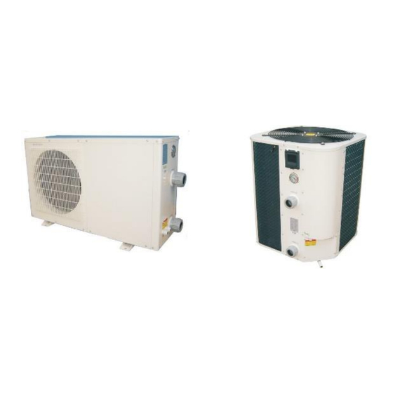
- Page 1 Swimming Pool Heat pump Instruction manual – Harmo PAC series (Type ZVWX1017, ZVWX1023, ZVWX1033, ZVWX1042, ZVWX1052, ZVWX1057, ZVWX1062) Imported by : Zwembad BVBA Industrieweg 9 3190 Boortmeerbeek België www.harmopool.eu...
-
Page 2: Table Of Contents
Table of contents Table of contents ................................. 2 Introduction ................................... 3 Characteristics ................................3 Safety instructions ................................. 3 Safety test ................................. 4 Specifications ................................. 4 Installation ..................................5 Accessories needed for the installation ........................5 Location ..................................5 Distance ..................................6 Installation of the valve ............................. -
Page 3: Introduction
Introduction Read the manual carefully before you open or maintain the heat pump. The manufacturer of this product will not be held responsible for injuries or damage to the unit, as a result of improper installation, debugging or unnecessary maintenance. It is essential that the instructions of this manual are followed at all times. Qualified personnel must install the heat pump. -
Page 4: Safety Test
Safety test Use the wiring diagram in the manual. Plug into the socket. Press the RESET button. The indicator "ON" is highlighted. Press the "TEST" button. The indicator "ON” will be turned off. Press the RESET button in order to use the device. Do not use if above test fails. Specifications Product code: ZVWX1017... -
Page 5: Installation
Installation Accessories needed for the installation The factory only provides the heat pump. Other necessary items that could be mentioned in the illustrations are to be provided by the user or installer. Attention! Please follow the following steps when installing the heat pump: ○... -
Page 6: Distance
Distance Install the heat pump as close to the swimming pool as possible to minimize the loss of heat through the piping. Put it on a solid base and place some rubber blocks under the heat pump to eliminate vibrations. Normally, the heat pump is installed within a 7,5 meter radius of the pool. -
Page 7: Installation Of The Pool System
Installation of the pool system Installation of the bypass With the bypass set correctly, your heat pump will deliver its best performance. The bypass has to be built as shown below: Setting the valves of the by-pass: Install the bypass with all 3 valves entirely open ○... -
Page 8: Electrical Wiring
Electrical wiring The heat pump is delivered without plug. For the electrical connection of the heat pump use the connectors L, N and grounding. Connections 1 and 2 are signal connectors from the filter pump to the heat pump. If this connection is used, the heat pump will switch off automatically when the filter pump is switched off. -
Page 9: Start-Up Procedure
Start-up procedure Start-up Procedure - after the installation is completed, you should follow these steps: 1. Turn on your filter pump. Check for water leaks and verify the flow to and from the pool. 2. Turn on the electrical power supply to the heat pump and turn the heat pump ON with the switch. The heat pump will start after the time delay period has lapsed. -
Page 10: Winter-Ready
Winter-ready Failure to winterize the heat pump could cause damage to the heat pump and will void warranty. In areas where freezing temperatures occur, you should protect your pump, filter and heat pump. Perform the following steps to completely drain the heat pump: Turn off the electrical power to the heat pump at the main breaker panel. -
Page 11: Display Settings
The heat pump will produce condensation (water) operating. The heat pump base is designed to allow the condensation to exit through the bottom drain port. The condensation will increase as the outdoor air humidity level increases. Check the following at regular intervals to ensure proper condensate drainage: Visually inspect and clear the bottom drain port of any debris that could clog the port. -
Page 12: Clock Settings
Press "M" again "8" "1 " Press “SET” to enter Mode setting, press to alter. Press “SET” again to confirm. Press "M" again "9" "0 " Press “SET” to enter water pump setting, press to alter. Press “SET” again to confirm. Press "M" again "A" "40 " Press “SET” to enter return water temp. setting, press alter. -
Page 13: Functions Of The Display
Functions of the display o Under standby status, press M button 5s to enter Operation Parameter setting interface;" " o Press"M"again to start setting (parameter from 00-D,see the Operation Parameter Table); o Under parameter setting, press to set data; o Please note no motion on the display for 10s,the LCD will display water-in/water out temp.(under running)or ambient temp.(under standby status) o Under running status, you can press M"... -
Page 15: Current Status
Current status Ambient temp. Under running status, press “M” 5 seconds to check the status of the unit. You can check water- in/water out temp, condenser temp and ambient temp, please note no motion on the display for 10s, the LCD will display water-in/water out temp/ (under running) or1ambient temp. (unit stops). Maintenance o Check the water supply to the unit often. -
Page 16: Appendix Wiring Diagram
Appendix wiring diagram Model ZVWX1017 – ZVWX1023... - Page 17 Model ZVWX1033...
- Page 18 Model ZVWX1042 – ZVWX1052...
- Page 19 Model ZVWX1052 – ZVWX1062...

Need help?
Do you have a question about the Harmo PAC Series and is the answer not in the manual?
Questions and answers
Hoe sluit ik de ZVWX 1033 elektrisch aan ? Heb 5 klemmen, de middenste is de aarding ? Bij de 2 rechtse staat pump ? Steek ik spanning op de 2 linkse en voedt ik dan over de warmtepomp de filterpomp met de 2 rechtse, dit is me niet duidelijk. Graag verduidelijking. grts Christian
To connect the Harmopool Harmo PAC Series ZVWX1033 electrically, refer to the wiring diagram specific to Model ZVWX1033, which is located on page 17 of the manual. Follow the diagram carefully and ensure all electrical work is performed by a certified technician.
This answer is automatically generated