Advertisement
Quick Links
installation and
servicing
Your Ideal installation and servicing guide
See reverse for
Models F320, F400, F480, F560
When replacing any part on this appliance, use only spare parts that you can be
assured conform to the safety and performance specification that we require. Do not
use reconditioned or copy parts that have not been clearly authorised by Ideal Boilers.
February 2010 UIN 202863 A06
xtra
users guide
xtra
Advertisement

Related Manuals for IDEAL imax xtra F400


Summary of Contents for IDEAL imax xtra F400
- Page 1 When replacing any part on this appliance, use only spare parts that you can be assured conform to the safety and performance specification that we require. Do not use reconditioned or copy parts that have not been clearly authorised by Ideal Boilers. February 2010 UIN 202863 A06...
- Page 2 For ft/h divide the gross heat input (Btu/h) by the gross C.V. Any direct connection of a control device not approved by Ideal of the gas (Btu/ft Stelrad Group could invalidate the certification and the normal appliance warranty. It could also infringe the Gas Safety HEALTH &...
- Page 3 GENERAL xtra CONTENTS Natural Gas only PI No. 0063 BR 3123 Boiler Assembly - exploded view........11 Destination Countries: GB, IE Boiler Clearances............. 9 Boiler Dimensions............7,8,9 Commissioning and Testing.......... 37 Electrical Connections........... 18 Electrical Supply............... 6 Fault Finding.
- Page 4 GENERAL INTRODUCTION Detailed recommendations are contained in the following Standards and Codes of Practice: boilers are fully automatically controlled, floor xtra BS. 5854 Flue and flue Structures in Buildings. standing, fanned, super efficient condensing appliances. BS. 6644 Installation of gas fired hot water boilers of rated The imax xtra comprises of 2 modules, Master and Slave.
- Page 5 Advice regarding the availability of proprietary types of FLUE SYSTEM DESIGN flue system can be obtained by contacting Ideal Stelrad Group. Due to the high efficiency of these boilers, the flue gas All joints or connections in the flue system must be impervious temperatures are low and the buoyancy in the stack will be to condensate leakage.
- Page 6 Heating Systems. through roof spaces and ventilated underfloor spaces. Ideal Stelrad Group recommend the use of Fernox Copal or The boiler must be vented. There must be no low points MB1 or GE Betz Sentinel X100 inhibitors and associated water...
- Page 7 GENERAL BOILER DIMENSIONS AND CONNECTIONS - HORIZONTAL FLUE CONNECTION KIT FITTED All dimensions shown in mm SIDE VIEW FRONT VIEW 17 (Condensate Drain) G (Flow & Return) Slave Module Master Module 113 (Air Inlet) 91 (Gas) REAR VIEW Flow Connections R2"...
- Page 8 GENERAL CONT'D...BOILER DIMENSIONS AND CONNECTIONS - VERTICAL FLUE CONNECTION KIT FITTED All dimensions shown in mm Condensate Drain SIDE VIEW FRONT VIEW Slave Module Master Module PLAN VIEW REAR VIEW Boiler Size im9616 Return Connection R2" Air Inlet Ducts O110 Installation &...
- Page 9 GENERAL BOILER DIMENSIONS AND CONNECTIONS (Optional water and gas header kit and rs air duct connector (F320 & F400 only) fitted) Note. F320 Model shown All dimensions shown in mm REAR VIEW SIDE VIEW Flow connection Return connection im9159 BOILER CLEARANCES The minimum dimensions as indicated must be respected to Left Side: 450mm ensure good access around the boiler.
- Page 10 Feed see notes position or raise the cistern above the minimum requirement specified by Ideal Stelrad Group. The isolation valves should be fitted as close to the pump as possible. System The information provided is based on the following assumptions:...
- Page 11 INSTALLATION BOILER ASSEMBLY im8496 Data Plate Legend 2. Burner switch 14. Damper Relay Board 31. Thermistor (flow) 3. Pressure gauge 19. Union Gas cock 33. Air pressure switch 8. Fan 20. Levelling feet 37. Relay 9. Gas Valve 22. Heat exchanger 38.
- Page 12 INSTALLATION PACKAGING REMOVAL / REMOVAL FROM PALLET The boiler comprises of an equally sized Master To unpack the modules: and Slave Module, separately packed on their Carefully remove the straps, and lift off the casing assembly pack - own pallets. This allows the boiler to be master only.
- Page 13 INSTALLATION ASSEMBLING THE MODULES 1. Fit spacers x 4 to the LH side corners of the Master Module chassis (located inside casing assembly pack). Spacers (x4) 2. Control Fascia Panel - Master Module: Remove the 2 3. Release the ribbon cable from the display board. screws securing the control fascia panel.
- Page 14 INSTALLATION 10 ASSEMBLING THE MODULES ..CONTINUED 7. Position Master Module and level feet using a 13mm spanner. Check module with spirit level. IMPORTANT. ENSURE MODULE IS LEVEL IN BOTH DIRECTIONS TO ENSURE SATISFACTORY ASSEMBLY. 8. Position Slave Module to LH side of Master Module (ensuring not to disturb levelled Master Module) and repeat levelling process.
- Page 15 INSTALLATION 11 ASSEMBLING THE MODULES ..CONTINUED 11. Remove 4 screws on each rear gas pipe support 12. Replace with the one piece rear gas pipe support channel and channel and discard channels. secure with 6 screws (located in casing assembly pack). 13.
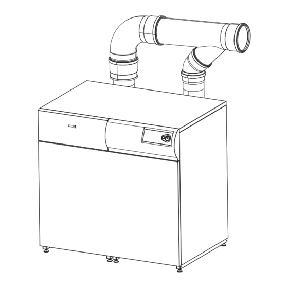
- Page 16 INSTALLATION 12 FLUE / AIR DUCT INSTALLATION See Table on page 5 for guidance on maximum permissible AIR DUCT flue and air duct system design. Combustion air can be drawn directly from the boiler room FLUE using the high level air inlet kit provided or ducted in from outside the building in which the boiler is installed.
- Page 17 INSTALLATION 12 AIR DUCT CONT'D..Where ducting the air from outside is not practical it can be fig 1 drawn from the boiler room by assembling the air inlet pipework as follows into the configuration shown in fig 1 & 2. 1.
- Page 18 INSTALLATION 13 CONDENSATE DRAIN (Slave and Master) If the vertical flue header is specified the flue manifold A condensate drain must be connected to the condensate drain connection must also be connected in the condensate bulk head connector on the back of each same manner.
- Page 19 INSTALLATION 15 FROST PROTECTION Central heating systems fitted wholly inside the building do The boiler has built into its control system the facility to protect the boiler only against freezing. not normally require frost protection as the building acts as a 'storage heater' and can normally be left at least 24 hours If the boiler flow temperature T , falls below 7...
- Page 20 INSTALLATION 19 INSTALLER CONNECTIONS MASTER MODULE Optional volt free connections for 230V AC boiler alarm during lock out condition. (Closed circuit during lock out) permanent mains supply Optional connections for programmable room stat and modulating sequencer kits 230V AC output for CH Optional connections for outside system pump.
- Page 21 INSTALLATION 21 DHW CONTROLS CONNECTIONS If the boiler is providing both CH and DHW, and the CH circuit DHW heat demand can be controlled by: is to operate for periods at a reduced temperature (i.e. 1. ON/OFF using a 230V switched to live 'DHW call' terminal weather compensated), then it is necessary to differentiate (e.g.
- Page 22 INSTALLATION 24 PICTORIAL WIRING DIAGRAM (MASTER BOILER) Installation & Servicing xtra...
- Page 23 INSTALLATION 25 PICTORIAL WIRING DIAGRAM (SLAVE BOILER) Installation & Servicing xtra...
- Page 24 230 VAC Permanent Permanent Alternatives: The mains supply mains supply If either pump requires more than Ideal programmable 1 amp supply current, connection must be made via a relay room thermostat and outside sensor kit External 230 VAC provides enhanced Programmer * user comfort.
- Page 25 Parameter 46 = 23 If a live output is required for positioning of the valve to satisfy DHW demand. Alternatives: The Ideal programmable room thermostat and outside sensor kit provides enhanced user comfort. Full instructions provided with kits. Installation & Servicing...
- Page 26 INSTALLATION 29 EXAMPLES OF HEATING SYSTEMS Heating system with DHW production (storage tank Output = Boiler Output) and mixing header. 3 way diverting valve Heating System Flow Pump Storage Heating circuit tank output boiler output Return im8196 Filter Primary Mixing System Header Pump...
- Page 27 INSTALLATION 30 BASIC CONTROLS DISPLAY (MASTER PANEL SHOWN) Both Master and Slave Modules employ a control panel. Slave control panel can be fully accessed by first removing cover (see Frame 52). MASTER MODULE CONTROL PANEL A. Burner switch B. Pressure gauge C.
- Page 28 INSTALLATION 31 STANDARD CONTROLS ACCESS Modes of Operation The standby, parameter and information modes are accessible without the service code. Standby Mode S t b y The standby mode will be shown after start up or reset of the Module control box. If no buttons are pressed for 20 minutes the display will automatically be set to standby mode.
- Page 29 INSTALLATION 32 STANDARD CONTROLS ACCESS CONT'D Info Mode I N F O Info mode is entered from standby mode by pressing the 'mode' button twice. Press Display P A R A I N F O Press the step button until the desired information is displayed. The dot after the 1st digit will be flashing indicating the Module is in 'info' mode.
- Page 30 INSTALLATION 33 STANDARD CONTROLS ACCESS CONT'D Info mode cont'd..Press Display Description b. 0. 0 C. 8 2 Heat Exchanger Temperature T7 ( Rate of increase in Temperature T7 ( C/s) 0. 1 E. 0. 1 Ionisation Current (micro amps) F.
- Page 31 INSTALLATION 34 STANDARD CONTROLS ACCESS CONT'D Info mode cont'd..Press Display Description Burner Run Hours, DHW N. 0 0 100 thousands/10 thousands Burner Run Hours, DHW thousands/hundreds Burner Run Hours, DHW tens/units Service Mode L 6 0 H 8 0 It is possible for servicing purposes to run the boiler on maximum or minimum loads.
- Page 32 INSTALLATION 35 ADVANCED CONTROLS ACCESS There is little requirement for advanced controls access as factory preset values are satisfactory for most parameters. If parameter changes are required with the optional kits then further instructions are provided with them. This mode must only be entered by a competent engineer. This level of access MUST NOT be entered by the user. Code Mode C O D E By entering the service code the following additional features are accessible:...
- Page 33 INSTALLATION 36 ADVANCED CONTROLS ACCESS CONT'D Lower Upper Factory Press Display Description Limit Limit Setting P A R A 1. 6 0 Do not Do not adjust adjust DHW System 00 = Off 01 = On 2. 0 1 02 = Off + pump continuous 03 = On + pump continuous CH System 00 = Off...
- Page 34 INSTALLATION 37 ADVANCED CONTROLS ACCESS CONT'D Lower Upper Factory Press Display Description Limit Limit Setting Booster time (minutes) note 00 = Off CH flow parallel shift For use with outside temperature sensor Do not Do not adjust adjust Maximum fan speed CH (hundreds) F320 F400 F480 Do not...
- Page 35 INSTALLATION 38 ADVANCED CONTROLS ACCESS CONT'D Lower Upper Factory Press Display Description Limit Limit Setting Forced low time (x 9 seconds) Do not Do not adjust adjust TIME - Temp. differential between flow temp & set point at which slow start ends. Slow start TIME - Modulation rate in slow start X 400rpm/min CH post pump time (minutes)
- Page 36 INSTALLATION ADVANCED CONTROLS ACCESS CONT'D Lower Upper Factory Press Display Description Limit Limit Setting CH type Do not Do not adjust adjust DHW type x0=N/A x1=N/A x2=N/A x3=N/A x4=N/A x5=N/A x6=N/A x7=N/A x8=N/A x9=DHW ON/OFF call for heat 0x=3 way valve normally open 1x=hot water pump 2x=3way valve normally closed Manual fanspeed (for service use)
- Page 37 INSTALLATION 41 FAN MODE (with code) Press Display Description F A N Fan speed 4 8 0 0 Actual fan speed e.g. 5500rpm 42 COMMUNICATION MODE (with code) Press Display Description C O N N In this mode the communication between the boiler control module, optional control interface. No communication FLASHING There is only communication between the boiler control module and controls interface kit.
- Page 38 INSTALLATION 45 COMMISSIONING AND TESTING A. ELECTRICAL INSTALLATION B. GAS INSTALLATION 1. The whole of the gas installation, including the meter, 1. Checks to ensure electrical safety should be carried out should be inspected and tested for soundness and by a competent person. then purged in accordance with the recommendations 2.
- Page 39 5. Remove and inspect the fan/venturi assembly. Refer to Ideal Stelrad Group does not accept any liability resulting from Frame 53. the use of unauthorised parts or the repair and servicing of 6.
- Page 40 SERVICING 51 GAS VALVE ADJUSTMENT The boiler contains 2 Modules with individual gas valves. Both must be adjusted. Maximum rate adjustment Minimum rate adjustment 1. Switch the boiler on and operate for 10 minutes. 9. To ensure the boiler operates at minimum rate without modulating, set the fan speeds to minimum.
- Page 41 SERVICING 52 CASING REMOVAL AND ACCESS Front Panels 2. Loosen 3 screws on one side of the inner front panel and undo the 3 screws from the other side. The 1. Pull the front panel forwards at the top, lift off the panel will now slide to one side for removal.
- Page 42 SERVICING 53 REMOVAL OF FAN / VENTURI INSPECTION 1. Refer to Frame 49. 2. Remove the jacket front, inner front, jacket right, jacket top and controls fascia panels. (Refer to Frame 52). 3. Disconnect the electrical connections from the fan. 4.
- Page 43 SERVICING 55 REMOVAL / CLEANING OF BURNER 1. Refer to Frame 49. 2. Refer to Frame 54 for removal of burner manifold. 3. Remove the gasket from the 4 studs. 4. Draw the burner out of the heat exchanger. 5. The burner can be cleaned on the inside surface using a soft brush and/or vacuum.
- Page 44 SERVICING 57 REMOVAL OF SUMP COVER 1. Refer to Frame 49. 2. Remove the jacket front and inner front panels. (Refer to Frame 52). 3. Remove the 6 nuts and withdraw the sump cover plate taking care to retain the gasket. 4.
- Page 45 SERVICING 59 GAS VALVE REPLACEMENT 1. Refer to Frame 49. 2. Remove the jacket front, inner front and control fascia panels. (Refer to Frame 52). 3. Remove the 4 screws securing the controls fascia support bracket and withdraw. 4. Disconnect the electrical connections from the gas valve.
- Page 46 SERVICING 61 IGNITION/DETECTION ELECTRODE TESTING/REPLACEMENT 1. Refer to Frame 49. 2. Remove the jacket front and inner front panels. Refer to Frame 52. 3. It is possible to measure the ionisation current with a voltmeter set at 0-10VDC. (0-10VDC = 0-10 micro amps ionisation current).
- Page 47 SERVICING 63 WATER PRESSURE SWITCH REPLACEMENT 1. Refer to Frame 49. 2. Remove the jacket front, control fascia, top and side panel. (Refer to Frame 52). 3. Isolate water circuit and drain boiler. 4. Pull off the electrical connections (no polarity) from the pressure switch.
- Page 48 SERVICING 65 TRANSFORMER REPLACEMENT 1. Refer to Frame 49. 2. Remove the jacket front, inner front, controls fascia and top panels. (Refer to Frame 52). 3. Disconnect the transformer connection from the boiler control module. (Refer to 'A' in Frame 66). 4.
- Page 49 SERVICING 67 OT CENTER REPLACEMENT 1. Refer to Frame 49. 2. Remove the front and inner front panels (Refer to Frame 52). 3. Squeeze tab and pull to remove connection lead. 4. Firmly pull up and down on module to remove.
- Page 50 SERVICING 69 MOTORISED DAMPER MOTOR REPLACEMENT 1. Refer to Frame 49. 2. Loosen 2 securing screws from motor cover and remove cover. 3. Disconnect electrical connections. 4. Remove 2 x M5 nuts and washers located behind mounting plate and remove motor. 5.
- Page 51 FAULT FINDING Detailed instructions on the replacement of faulty components Before attempting any electrical fault finding ALWAYS carry out are contained in the 'Servicing' section of these Installation & the preliminary electrical system checks as detailed in the Servicing Instructions. Instructions for the British Gas Multimeter or other similar commercially available meter.
- Page 52 FAULT FINDING MASTER AND SLAVE BOILER CONTROL MODULE ERROR CODES Code Description Action FUSE 24V circuit dead Check Transformer & replace if necessary Check 24V fuse on Control Board If 24V fuse blown check for short circuits before replacing Flame Error (signal present when there should not be) Replace Control Module No ignition after restart Check inlet gas pressure...
- Page 53 FAULT FINDING MASTER AND SLAVE BOILER CONTROL MODULE ERROR CODES CONTINUED Code Description Action Incorrect tacho signal from fan Check wiring to fan. If wiring OK replace fan. Flow/return temperature differential too high Check no air in system or boiler Check adequate flow of water through boiler Flow thermistor short circuit Check wiring...
- Page 54 FAULT FINDING MASTER AND SLAVE BOILER CONTROL MODULE BLOCKING CODES Code Description Action Air Pressure Switch did not close Check motorised damper operating Check air damper is opening Check flue for blockage Check/clean burner Check Air Pressure Switch sensing pipes condition Check fan speed Check air Pressure Switch &...
- Page 55 When replacing any part on this appliance use only spare parts that you can be assured conform to the safety and performance specification that we require. Do not use reconditioned or copy parts that have not been clearly authorised by Ideal boilers.
- Page 56 SHORT LIST OF PARTS 72 SHORT LIST 51 & 52 im8475b Installation & Servicing xtra...
- Page 57 NOTES Installation & Servicing xtra...
- Page 58 NOTES Installation & Servicing xtra...
- Page 59 NOTES Installation & Servicing xtra...
- Page 60 Technical Training The Ideal Boilers Technical Training Centre offers a series of first class training courses for domestic, commercial and industrial heating installers, engineers and system specifiers. For details of courses please ring: ..01482 498 432 Ideal Boilers, P.O. Box 103, National Ave, Kingston upon Hull, HU5 4JN.
Need help?
Do you have a question about the imax xtra F400 and is the answer not in the manual?
Questions and answers