Table of Contents
Advertisement
Advertisement
Table of Contents

Related Manuals for Thrane&Thrane Sailor CU5100 MF


Summary of Contents for Thrane&Thrane Sailor CU5100 MF
- Page 1 USER MANUAL SAILOR CU5100 MF/HF Radiotelephone...
-
Page 3: Introduction
Introduction Congratulations on your new SAILOR CU5100 MF/HF maritime radio telephone with built-in DSC (Digital Selective Calling) system, fulfilling the highest international standards for marine MF/HF communication and safety procedures. The transceiver is born with a 2187,5kHz DSC watch receiver forming an ideal system for MF GMDSS installations. The transceiver can easily be upgraded for 6 channel scanning DSC watch receiver and Telex operation to comply with MF/HF requiements in sea area A3. -
Page 4: Abbreviations Used In This Manual
Abbreviations used in this manual ADDR Address Automatic Gain Control Amplitude Modulation Automatic Repetition reQuest CLRF Clarify Control Unit DIRTLX Direct Telex Digital Selective Calling ETSI European Telecommunications Standards Institute Forward Error Correction Go Ahead GMDSS Global Maritime Distress and Safety System Global Positioning System High Frequency Single sideband - full carrier... -
Page 5: Quick Dsc Distress Call
Quick DSC distress call (only for emergency use) 1. If necessary, switch on by pressing the ON/OFF button 2. Lift up the lid covering the orange key and press for 3 seconds. 3. The distress will be accompanied by a sound. Distress message is sent at the continuous tone. -
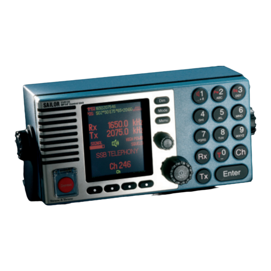
Page 6: The Mf/Hf At A Glance (Cu5100)
The MF/HF at a glance (CU5100) 1. Display. 7. DISTRESS button. 2. Dimming button. Protected by shield. To use, 3. Mode button. lift the shield and press for 3 seconds. Toggles between 8. Soft keys. SSB TELEPHONY, The function of each key is described in AM BROADCAST, its respective field in the display above DSC,... -
Page 7: Table Of Contents
Contents Introduction ..........................iii About this manual ........................ iii Abbreviations used in this manual ..................iv Quick DSC distress call ......................v Mayday procedure ........................v The MF/HF at a glance (CU5100) ................... vi MF/HF Fundamental info ....................3 Basic functions ........................4 Powering MF/HF ...................... - Page 8 Data call ..........................39 Scanning ........................... 40 Watch keeping receiver ....................41 Watch receiver setup ....................41 10 Menu tree .......................... 42 11 Installation ........................43 11.1 Compass safe distance .................... 43 11.2 Dimensions and weight .................... 43 0725...
-
Page 9: Mf/Hf Fundamental Info
1 MF/HF Fundamental info Propagation of MF and HF Radio Waves. MF/HF radiocommunications provide a medium and long range service. The 1.6-4 MHz marine band is intended primarily for coastal operation beyond normal VHF communication range. A reliable range of more than 150 nautical miles can be expected in most areas in the daytime, more in the nighttime. -
Page 10: Basic Functions
2 Basic functions Powering MF/HF The MF/HF is turned on by a single press on the ON/OFF/Volume button. The MF/HF is turned off by pressing the ON/OFF/Volume button for 4 seconds. Always indicated by a count down window in the information display, except if the radio is powered down in distress mode. -
Page 11: Dimming
Dimming To adjust backlight intensity the dim button is pressed. Change mode With the mode button different operation modes can be selected. Toggle the button to choose between SSB TELEPHONY, AM BROADCAST, DSC, TELEX(Option) and SSB REMOTE. Note: When in AM BROADCAST mode the transceiver cannot be keyed. How to operate the menu Press the Menu button Main menu:... -
Page 12: How To Make A Call To A Coast Station
How to make a call to a coast station Wait until transmission of the traffic list has finished and the channel is free. Call the coast station on the working frequency on which the traffic list was received or as instructed by the coast station. -
Page 13: Voice Call Operation
3 Voice call operation Operating MF/HF radio communication The MF/HF is operated by means of a handset. To bring the MF/HF in transmission mode the handset must be hooked off and the PTT button on the handset has to be pressed. Transmission is indicated by the lighted TX indicator. -
Page 14: Enter Rx/Tx Frequency
Enter Rx/Tx frequency Press RX to enter a new Rx frequency. Enter the new frequency via the keyboard or roll up and down with the Adjust/ Tune knob. Complete by pressing Enter. Pressing the ENTER softkey is equal to pressing OK Press TX to enter a new Tx frequency. -
Page 15: Channel Entry
Channel entry 3.4.1 Select a channel The MF/HF control unit has all ITU channels preprogrammed in a channel table. These channels starts at Ch 241 and ends at Ch 2517. Channel 1 to 199 are reserved as user channels. Press Ch and key in an existing channel number. Complete by pressing Enter or by pressing the ENTER softkey. - Page 16 3.4.2 Store a channel Select the desired RX frequency, TX frequency and mode setting. Press Ch and key in a channel number between 1 and 199. softkey, deletes the previous entry STORE softkey, stores the channel CANCEL softkey, selects the previous display If the channel number is free, press the STORE softkey to store the channel.
-
Page 17: Select A Channel From The Station Table
3.4.4 Replace a channel Select the desired RX frequency, TX frequency and mode setting. Press Ch and key in a channel number between 1 and 199. Press the REPLACE softkey to store the channel. softkey, deletes the previous entry REPLACE softkey, to convert to the new RX and TX frequencies. -
Page 18: Re-Tune The Antenna Tuner
Re-tune the Antenna tuner Press the button ‘0’ for re-tuning the antenna tuner. Also TX tuning is done automatically the first time the transmitter is keyed on a new frequency and before any DSC transmission. 0725... -
Page 19: Dsc Operation
4 DSC operation DSC main Press the Menu button Using the Down key and press OK when the select bar is at the preferred menu, or use quick select. DSC CALL - Alternative press Mode button until DSC mode, and press DSC CALL softkey. DSC CALL Select 1. -
Page 20: Dsc Setup
DSC setup Press the Menu button Select 5. SETUP. Select 1. DSC SETUP. Use CHANGE softkey - to change setup Steps to the next Use CANCEL softkey - to return to previous display Change LAT/LON - to manually enter position if no GPS position Change UTC - to set real time clock if no GPS time and date TIME and POS disappear when information is updated via the NMEA interface. - Page 21 Set answer back mode AUTO ACKNOWLEDGEMENT = ON: Transmission of acknowledgement is initiated automatically when a direct call, polling or position request call is received. AUTO ACKNOWLEDGEMENT = OFF: Manuel acknowledgement only. Direct calls initiated by the ship can be carried through; direct calls from coast stations cannot (factory default).
-
Page 22: Receiving A Distress Call
Receiving a Distress Call The DSC Watch Receiver keeps continuous watch on the distress and safety frequency 2187.5 kHz. Reception of a distress or urgency call is indicated by a specific sound signal which continues until a key is pressed. Additional DSC channels can be used if 6-channel scan has been enabled, see chapter 8. -
Page 23: Receiving An Individual Call
Receiving an Individual call When the transceiver is not used for traffic, scanning should be activated to keep watch on one or more DSC frequencies used for public correspondence and general ship-to-ship communication. Reception of an individual routine call addressed to the ship is indicated by a sound signal which continues until the call is acted upon. - Page 24 Direct Dial Calls: Some coast stations provide automatic connection from the public switched telephone network allowing a telephone subscriber to call the ship directly without operator intervention at the coast station. Note: Auto Acknowledgement must be On to allow automatic connection, see DSC Status Display.
-
Page 25: Sending A Test Call
Sending a test call This call type is intended for test of the DSC system on distress and safety frequencies. Press the Menu button. Select OK Select TEST CALL type Navigate the menu by using Up- and Down key Insert the number in the call Backspace, deletes last digit Selects a submenu where a prepro- grammed coast station can be selected... - Page 26 Start transmission of Select the DSC frequencies the call Steps between DSC distress frequencies Transmission of a DSC call on MF/HF takes approx. 8 seconds. The coast station should answer the call by sending a DSC Acknowledgement within 4 1/2 minutes. No further communication is intended to take place.
-
Page 27: Calling A Coast Station
Calling a coast station Press the Menu button and select 1. DSC CALL Select individual Select COAST STATION routine call type call type Some coast stations provide automatic connection with the public switched telephone network. To use this facility select PHONE NO and key in the telephone number. Otherwise: Key in the nine digit MMSI number of the wanted coast station. - Page 28 If the MMSI number is found in the station list, the frequencies are selected from the DSC frequencies of the station if any; otherwise from the list of non distress DSC frequencies. If DSC frequencies were selected from the Telephony display prior to the call these are default. Distress frequencies cannot be selected in any way.
-
Page 29: Calling A Ship
Calling a ship Press the Menu button and select 1. DSC CALL. select 2. SHIP. Key in the nine digit MMSI number of the wanted ship. Insert the number in the call Backspace, deletes last digit A working channel shall be proposed when calling another ship. Insert the working Select the DSC frequencies in the call... - Page 30 Normally 2177 kHz is used for intership DSC calls. In addition user programmed DSC frequencies may be selected. If DSC frequencies were selected from the Telephony display prior to the call these are default. Distress frequencies cannot be selected in any way. Transmission of a DSC call on MF/HF takes approx.
-
Page 31: Sending An Area Call
Sending an area call This call type is used for announcing a vital safety or urgency message. Press the Menu button and select 1. DSC CALL select 3. AREA Select Select Steps between S/N Steps between E/W Enter area radius Select (nm) softkey, delete the... - Page 32 Use softkey to select Insert the TX working mode frequency in the call Selects the telephony display for change of working frequencies The working frequency for safety calls is normally the distress and safety frequency in the same band as the DSC call, i.e. 2182 kHz on MF. Select the DSC Starts transmission frequencies...
-
Page 33: Repeat A Call
Repeat a call Press the Menu button and select 2. DSC LOG RE-SEND start Select TX call log transmission of the call Selects non-distress RX call log Selects Distress RX call log Returns to previous display The TX calls log has capacity for storing 20 transmitted calls. The oldest call is deleted when the capacity is exceeded. -
Page 34: Dsc Call Menu
4.10 DSC call menu MENU 1. DSC CALL 1. COAST STATION 1. WITH PHONE NO MMSI Phone no DSC freq 2. WITHOUT NO MMSI DSC freq 2. SHIP MMSI Working freq DSC freq 3. AREA RADIUS DISTRESS SSB TELEPHONY URGENCY NO INFORMATION Working freq DSC freq... -
Page 35: User Setup
5 User setup There is a number of special setups available as shown in the setup menu. To change a setup: Press the Menu button and select 5. SETUP Selects the type Steps up or down between selectable setups Returns to previous menu 0725... -
Page 36: Telex Operation
6 Telex operation For the MF/HF products a Telex option is available. The Telex option is enabled by entering of a pin-code (key) into the MF/HF transceiver. This pin code is uniquely matched to the serial number of the MF/HF transceiver, i.e. one specific pin code will enable the telex option in one specific MF/HF transceiver only. -
Page 37: Simple Telex Operation
Simple telex operation 6.2.1 Keyboard Keyboard Indicator Lamps ‘Standby’ Steady light indicates that the terminal is ready. Flashing light indicates that the printer is off or out-of-paper or the modem is busy/inhibited. Telex mode must be selected in the frequency display of the CU. ‘Tx’... - Page 38 Send Mesg (F5): Transmits (prints in Standby) the edited message. WRU (F6): During ARQ communication only: Requests the other station to transmit its answer-back code. DE (F7): Transmits own answer-back code, see the configuration printed when entering telex mode. Over (F8): Changes the direction of an ARQ connection.
- Page 39 6.2.4 Channel selection Press F1. The printer responds by printing: ‘ITU Coast station / interShip channel (C/S)?: After pressing ‘C’ or ‘S’ as desired the channel number is requested and must be typed in. The validity of the channel number is checked. If the channel number does not exist this is indicated.
- Page 40 Text may be added or deleted. Deletes the last word of the line Deletes message (after confirmation) Delete if pressed after Edit (F4) . Line numbers (10, 20, etc.) are added automatically when typing the message. 6.2.7 Receiving a message Reception is possible whenever the terminal is on, indicated by steady light in the ‘Standby’...
- Page 41 6.2.9 Example of ARQ Transmission to a Coast Station When the GMDSS telex terminal is on, indicated by the ‘Standby’ keyboard indicator lamp, and the radio is configured to the desired working channel (and, if requested by the coast station, free signal can be heard in the speaker), press the Call ARQ key. The printer responds by printing: Enter ARQ call code: Type in the call code, e.g.: 0832...
-
Page 42: Telex Via Data Terminal
Having completed the transmission, the answer-back code of the subscriber is requested by pressing the WRU key: 54321 ZYXW and own answer-back is sent by pressing the DE key: 123456789 abcd x To disconnect the land line type: kkkk The coast station responds with: Time: 07-06-20 12:48 Ship: 123456789 ABCD X Subscr: 54321... -
Page 43: Data Call
7 Data call Data service via MF/HF is offered by various service providers utilizing their individual application hardware and software external to the MF/HF equipment. To operate data service the MF/HF radio must have been prior configured to allow operator selection of Remote mode of operation. -
Page 44: Scanning
8 Scanning To start scanning the “4” button is pressed. The last used scanning type is selected and squelch is set to on when scanning is activated. Speaker is set to on if the scanning type is Telephony Watch, Multi Watch or Dual Watch. Scanning is stopped by pressing softkey EDIT or by lifting the handset off hook. -
Page 45: Watch Keeping Receiver
9 Watch keeping receiver For the MF/HF products a watch keeping option is available. The watch keeping option is enabled by entering of a pin-code (key) into the MF/HF transceiver. This pin code is uniquely matched to the serial number of the MF/HF transceiver, i.e. one specific pin code will enable the watch keeping option in one specific MF/HF transceiver only. -
Page 46: Menu Tree
10 Menu tree MENU 1. DSC CALL 1. COAST STATION 1. WITH PHONE NO 2. WITHOUT NO 2. SHIP 3. AREA 4. DISTRESS 1. ALERT 2. RELAY 1. COAST STATION 2. AREA 5. INDIVIDUAL 6. GROUP 7. TEST CALL 1. COAST STATION 2. -
Page 47: Installation
11 Installation 11.1 Compass safe distance Compass safe distance in accordance with ISO/R 694 are given below in metres. Unit Standard Steering 5.4°/H 18°/H Control Unit Handset Cradle 5070 Loudspeaker 11.2 Dimensions and weight Handset for transceiver Drilling plan * 120 Space for handset access This Handset has a hook-on/off function, which is activated by a small magnet embedded... - Page 48 Control unit The Control unit may be tabletop or bulkhead mounted. Control unit with mounting bracket 40536A Mounting option Drilling plan 4 x ø4 14.50 181.00 209.00 Tilting +/-45 ° Control unit connector panel Handset SCAN-BUS Printer Keyboard Data 40615 40616 Weight: Control Unit...
- Page 49 0725...
- Page 50 TT-98-124350-THR-A Issue: 0725 Thrane & Thrane A/S info@thrane.com www.thrane.com • •...
Need help?
Do you have a question about the Sailor CU5100 MF and is the answer not in the manual?
Questions and answers